Subsystems
This page explains main subsystems of Misasa Deep Space Station.
Overall
Antenna
Telecom
LNA
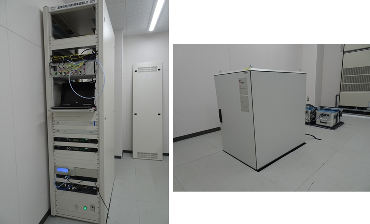
Time and Frequency Signal Generator
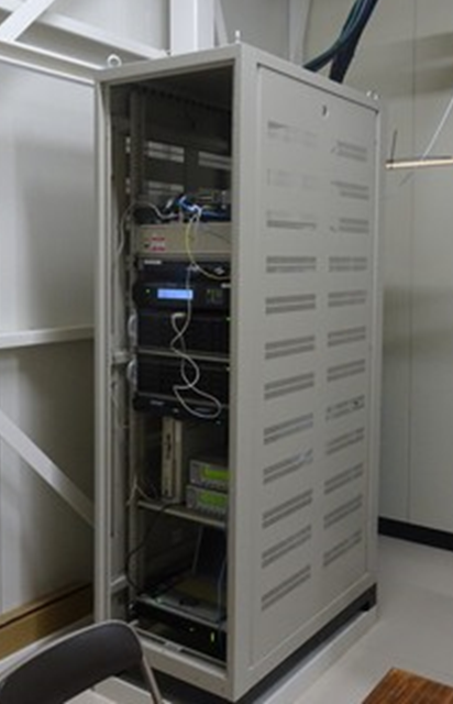
Open-loop Multi-band Receiver
Others
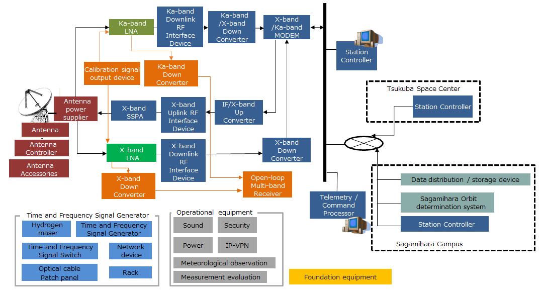
Overall Overview
The subsystem configuration of Misasa Deep Space Station is as follows, and the main subsystems are Antenna, Telecom, X-band LNA, Ka-band LNA, Time and Frequency Signal Generator, and Open-loop Multi-band Receiver.
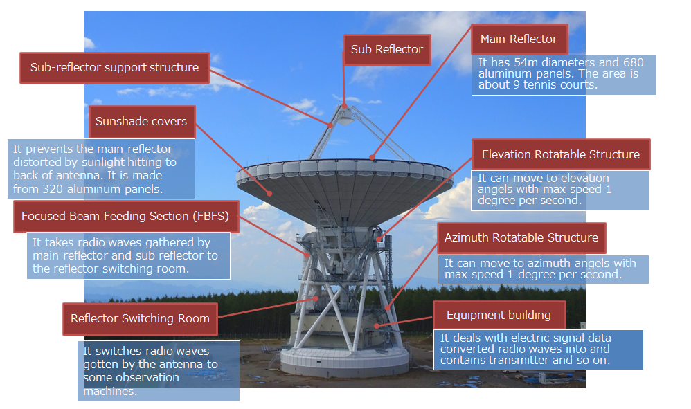
Antenna Subsystem
Antenna Subsystem gathers radio waves from noise spacecrafts from as much as possible. MDSS can receive not only X-band but also Ka-band.
Spec
Diameter |
Vertical: 54026.4mm |
Drive range |
Az:180deg±270deg |
Antenna drive machine |
|
G/T |
X-band: 54.69dB/K@EL=15deg |
Antenna gain |
X-band(UPLINK): 69.62 dBi |
Design life |
Over 20 years |
Weight |
2240tons Approx. |
See the User's guide for more details.
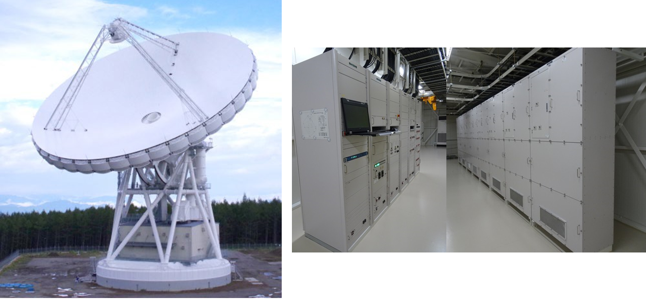
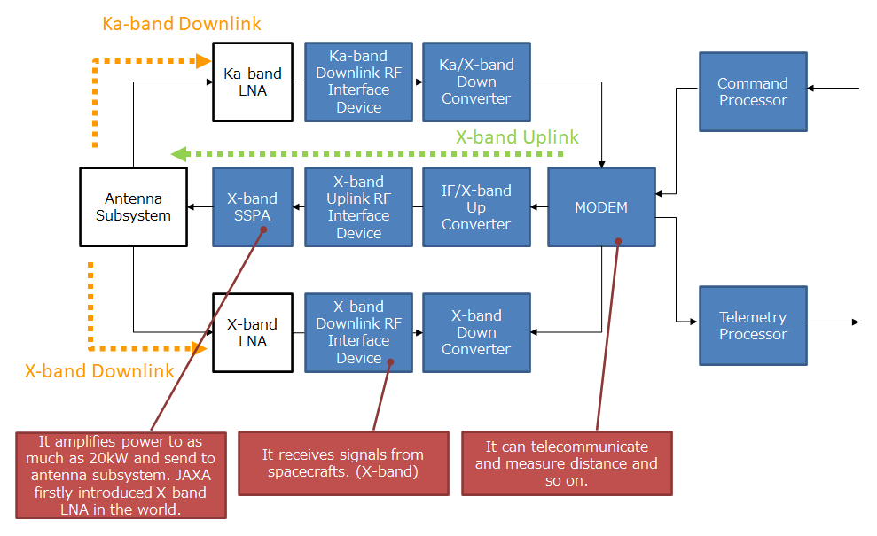
Telecom Subsystem
The telecom subsystem includes many components. Most of them are placed inside the alidade building. The telecom subsystem has the following functions.
- Receive and demodulate telemetry from the spacecraft and transmit it to the user. The modem is CCSDS compatible.
- >Amplify the command signals generated by the user and transmit them to the spacecraft.
Spec
Uplink Frequency |
7145-7235MHz |
Downlink Frequency |
X-band: 8400-8500MHz |
Supported polarization |
RHCP / LHCP |
Modulation type |
PCM-PSK-PM |
See the User's guide for more details.
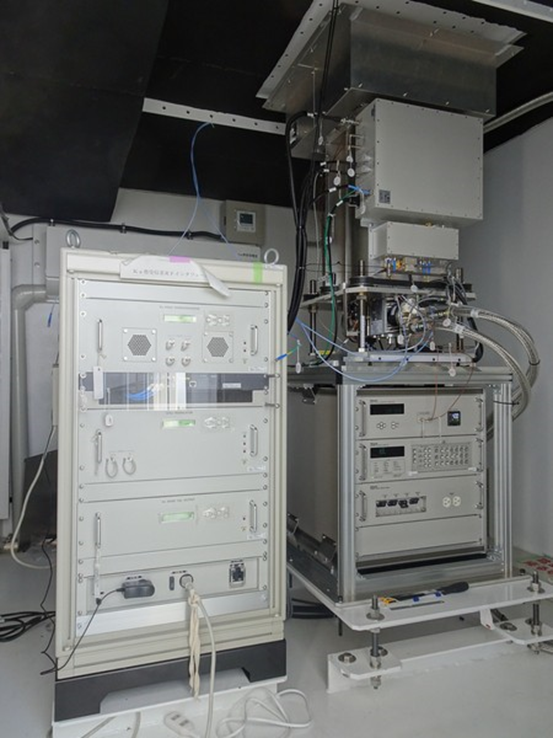
Low Noise Amplifier (LNA)
Low Noise Amplifier (LNA) expands signals gathered by antenna and transmits them to the Telecom subsystem.
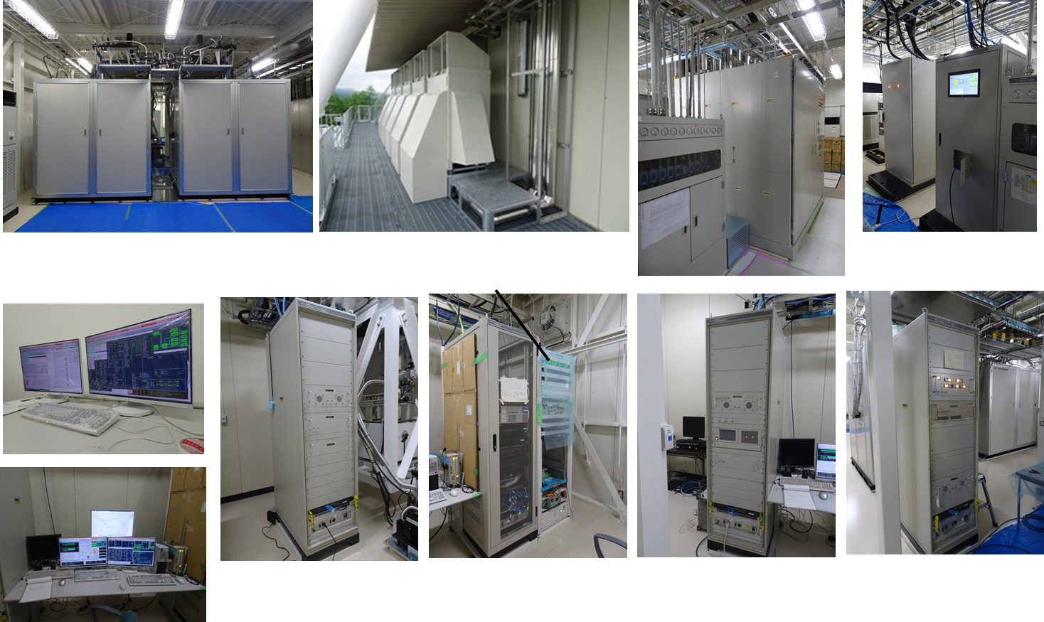
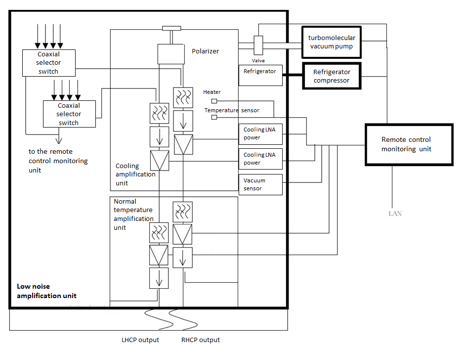
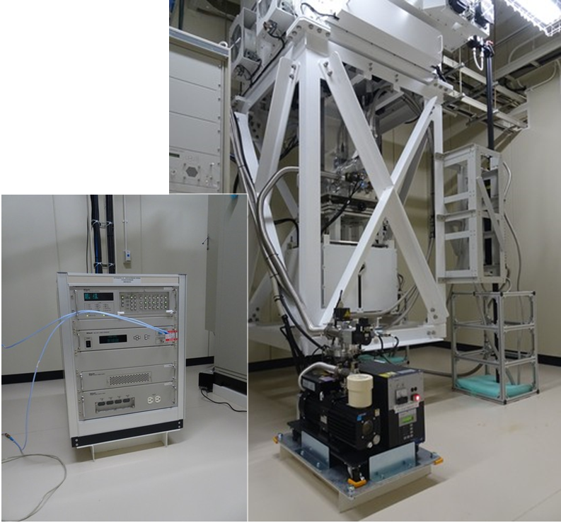
X-band LNA consists of the low noise amplification unit, the remote control monitoring unit, the refrigerator compressor and the turbomolecular vacuum pump. In order to achieve the required performance and the input equivalent noise temperature of less than 21K, the cooling amplifier of the low noise amplifier is cooled to the cryogenic temperature of -269°C (4K).
JAXA has manufactured and installed the first Ka-LNA for deep space exploration in Japan by JAXA in-house. The Ka-LNA uses a GM (Gifford-McMahon) refrigerator with gaseous helium for cryogenic cooling to reduce noise. X-LNA uses the same method, and the equipment of X-LNA and Ka-LNA are shared.
X-band Low Noise Amplifier
Ka-band Low Noise Amplifier (by JAXA in-house)
See the User's guide for more details.
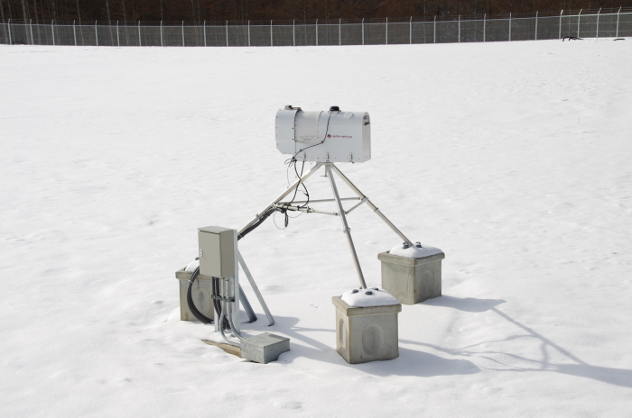
Other equipments
- GNSS receiver
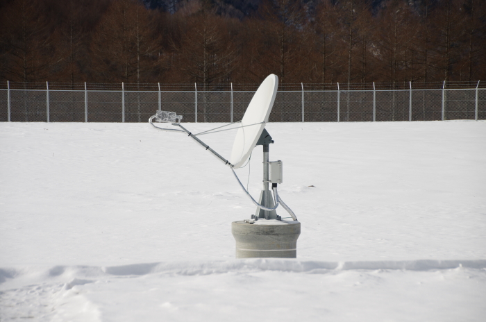
- Radio seeing monitor
- Water vapor radiometer
It is a monitor station for the Quasi-Zenith Satellite System and is expected to be a very useful observation station in the international positioning field because it colocates with the 54m antenna (VLBI observation station).
The acquired observation data is provided to the IGS (International GNSS Service) on a daily basis and utilized worldwide. This station is registered with the IGS as ID: MSSA00JPN.
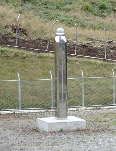
When radio waves pass through the earth's atmosphere, phase fluctuations called "radio seeing" occur. When the frequency is low, the radio seeing of the electron density in the ionosphere is the main factor. On the other hand, the higher the frequency, the more the water vapor density in the troposphere becomes the main factor. Large antennas such as MDSS, which handle high frequencies, are greatly affected during observation, so a radio seeing monitor device is installed to constantly monitor them.
At high frequencies, the amount of water vapor in the atmosphere affects the amount of radio wave attenuation, so a water vapor radiometer constantly monitors the state of water vapor in the atmosphere.