


TOP > Topics > 2004 > Flight experiment by a deployable flexible structure
![]()
Flight experiment by a deployable flexible structure
The collaboration team of ISAS, University of Tokyo and University of Kyushu has succeeded in the flight experiment for the reentry vehicle with a significantly low ballistic coefficient that is attained by a deployable flexible structure.
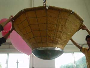
Such a vehicle is quite useful for a planetary exploration since the characteristics of the low ballistic coefficient enables the vehicle to allocate less weight for the heat shield structure. That is, the weight saving, thus attained, can be transferred to the payload capability. The fully deployed vehicle has a configuration of a blunted cone; of which base diameter and the half angle is 1.35 m and 45 degrees, respectively. The blunted part is composed of the metallic structure capsule, inside which a diagnostics equipment including the telemetry system is installed. The conical part is composed of a flexible membrane with a compression ring at the base. For the diagnostics, several measurements including an image of the membrane structure, taken by a onboard CCD camera with a fish eye lens, were carried out. Figure 1 shows an appearance of the fully deployed vehicle.
Fig. 1 Appearance of the fully deployed vehicle. |
The flight was intended to demonstrate the flight capability of the vehicle from the structural design point of view. For this purpose, the flight plan was arranged as a drop test from a high altitude of 40 km, which was carried out by means of a large scientific balloon. Therefore, the dynamic pressure environment attainable by the flight can be equivalent to that experienced for the reentry flight, even though the Mach number is relatively low.
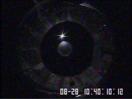
The drop test was carried out above the sea area 200km east from the Sanriku balloon center at a local time of 10:40 am in August 28, 2004. The flight was done as planned and was successful, which was immediately confirmed by the CCD image of not only the camera onboard the vehicle but also the camera onboard the gondola from which the vehicle was separated. Figure 2 an 3 show the image taken by the camera onboard the vehicle and the gondola, respectively, several seconds after the separation. In Fig. 2, the white sphere at the center of the image is the balloon from which the vehicle was separated, and a shining sun is also seen beside it. The surrounding donut shape part is the image of the flexible membrane. Since this image is taken by the fish-eye lens, the image is significantly deformed: the inner circle of the donut shape is the outer compression ring, and the outer circle of the donut corresponds to the attachment part of the membrane to the metallic capsule.
Fig. 2 Backward view taken by the camera onboard the vehicle |
In Fig. 3, the back side view of the vehicle, flying downward toward the sea is depicted. Some clouds are also seen underneath.
Fig. 3 Image of the vehicle flying downward towards the sea. |
Besides the image data, almost all the data were perfectly obtained for the diagnostics measurement though the onboard telemetry system. These data are quite useful to analyze the performance of the vehicle during the flight.
It is expected that the present success pushes forward the next stage development of the reentry vehicle of the present type.
September 9, 2004