


TOP > Report & Column > The Forefront of Space Science > 2015 > Forefront of the Materials Science and Engineering in Rocket Engine Development
![]()

Creep-fatigue Damage of the Combustion Chamber Wall of the Liquid Rocket Engines JAXA has been developing LE-9 engine for H3 Rocket, in which high reliability and extremely low costs are required (Figure 2 Left). Its combustion chamber has a double shell structure consisting of the inner cylinder made of the copper (Cu)-chromium (Cr)- zirconium (Zr) alloy and the outer cylinder heat resistant nickel alloy (Figure 2 Middle). The inner cylinder possesses cooling grooves for liquid hydrogen (LH2); the groove wall is exposed to the 3000°C burning gas and the -250°C LH2, and there happen large temperature changes and excessive thermal strain at start-up and shut-down processes. We have an experience that during the past ground firing tests of other engines, after around 20 combustion cycles, cracks were found on the LH2 side of the cooling groove (Figure 2 Right). Even the current, non-reusable rockets take flights with execution of several firing tests after engine fabrication, require crack detection, material degradation mechanism and residual life assessment indispensable for ensuring their reliability. 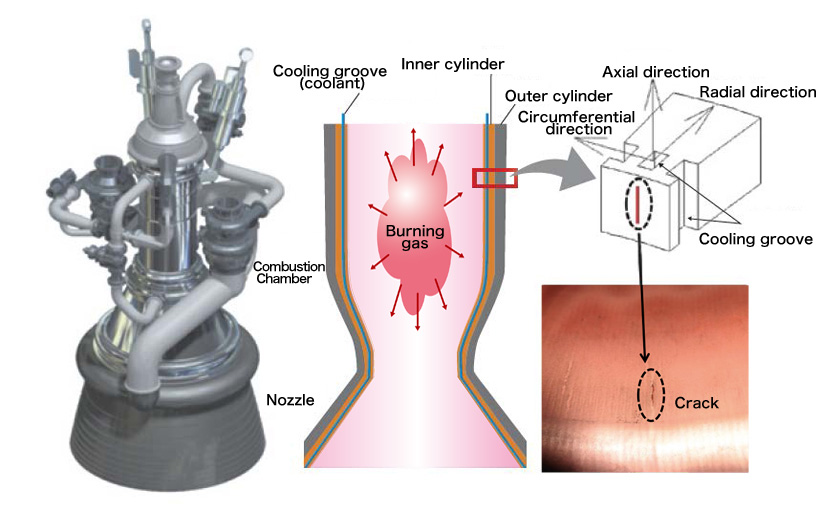
The Engineering Digital Innovation Center of JAXA conducted three-dimensional finite element analysis around the crack on the combustion chamber wall (Figure 3 Left). It was found that just after start-up the temperature of the combustion chamber rises rapidly to nearly 500°C, followed by the 270 s stable combustion and then the temperature drops rapidly after shut-down. With this process, the chamber wall would suffer from the compressive deformation and tensile deformation reaching the plastic region (*2) during the start-up and shut-down processes, and the extremely low speed tensile deformation (metallurgically similar to the tensile creep deformation) due to the slowly rising temperature of the outer cylinder during the stable combustion. Troubles are used to be reported in the power-plant pipes caused by creep-fatigue, (*3) but the fatigue amplitudes of those case do not reach the plastic region. Under the condition of rocket engine which possesses both large plastic strain in fatigue mode and creep strain in creep mode, the material fails within less than 20 cycles in the creep-fatigue test (Figure 3 Right). In the creep-fatigue test, the material fails within the lifetime shorter than 1/10 of that in the simple creep test and within the life-cycles smaller than half of that in the simple fatigue test. It means that the simple linear cumulative rule does not effective at all. 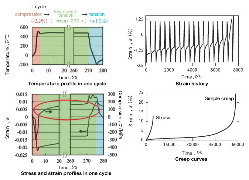
We observed the inside of the material during the creep-fatigue test to find the accumulation of the damages both in the creep mode (grain boundary voids) and the fatigue mode (fatigue cracks). The damage accumulation in creep-fatigue is understand as follows: the fatigue cracks are generated on the sample surface and develop toward the inside of the material through the grain boundary, on the other hand, the grain boundary voids are generated and grow in the inside of the material during creep, and finally the both damages join and causes rapid acceleration of material degradation. 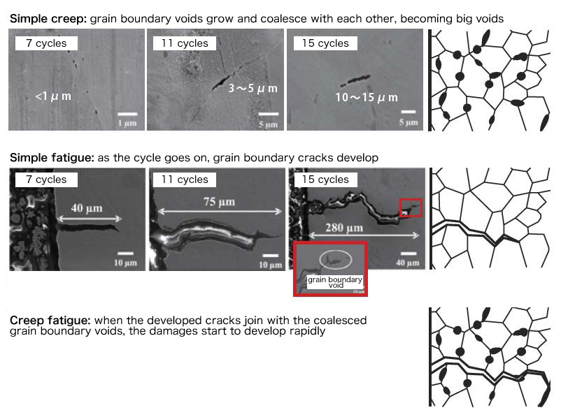
(*2) Plastic region: When a force is applied to a metallic material, at first it shows only elastic deformation, but from a certain time, plastic deformation takes place. (*3) Creep-fatigue: Among the loads that materials used to receive under high temperature, those that include creep phenomenon during cyclic deformation are called creep-fatigue, and they are one of the main reasons of material degradation in power plants.
|
||||||||||||||