


TOP > Report & Column > The Forefront of Space Science > 2006 > Quick Release on Experiment Results of Mesh Deployment and Phased Array Antenna by S-310-36
![]()

Active phased-array antenna experiment 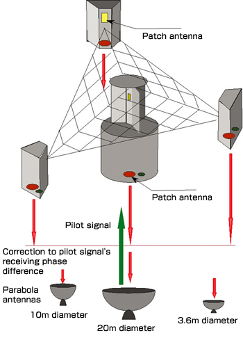
Fig. 5 illustrates the active phased-array antenna experiment by the S-310-36. The antenna is composed of antenna elements installed on the main satellite’s retro-directive system and three sub satellites. Each antenna is equipped with a receiver to receive pilot signals transmitted from the ground and a transmitter to send phase-controlled radiowaves to the ground. The retro-directive function can be verified by the following steps: transmit pilot signals from the 20m- diameter parabola antenna at Uchinoura; and receive the radiowave signals sent from the main and sub satellites at three parabola antennas with diameters 20m, 10m and 3.6m respectively. 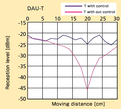
Fig. 6 shows part of the experiment’s results performed in the radiowave darkroom before the launch. Without the retro-directive function, the reception level drops greatly, as shown in the red line, because of the phase difference according to the sub satellite’ change of position. With the retro-directive function, on the other hand, the level is constantly maintained, as shown in the blue line, even if the sub satellite moves. The results suggest that, with the retro-directive method, our system would function as a phased-array antenna. Just after the experiment using the rocket, we started analysis based on the ranging data between main and sub satellites and measurement data on pilot-signal phase differences. Fig. 7 shows a measurement sample of pilot-signal phase difference. The phase changes as the sub satellites are released from the main satellite and, accordingly, transmission distance to the ground changes. This difference value is almost reasonable. In future, by analyzing the ranging data and reception data on the ground, we will verify whether the retro-directive function operated normally as designed. 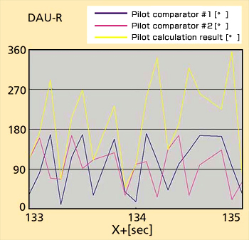
On-the-mesh moving system experiment After the mesh was deployed, we performed an experiment running the moving system on the mesh. The system uses permanent magnets to maintain the up/down position of its driving mechanism. In the microgravity experiment conducted onboard an aircraft in March 2005, the moving system ran on the mesh without any problem even in a microgravity environment. The experiment this time was conducted as part of space-engineering education for students. It was unique in that most of the experiment payloads were hand made by students. It was a great achievement that all the instruments operated normally. We believe that students learned a lot, such as the difficulty of producing instruments that function with certainty, through all the processes from ground tests to coupling tests, pre-launch checkup, launch and operation. We would like to express our sincere gratitude to the ISAS rocket team of Messrs. Inatani, Higuchi, Ishii and others, who participated patiently in our project and taught us a lot. (Shinichi NAKASUKA, Nobuyuki KAYA)
|
|||||||||