TOP > Report & Column > The Forefront of Space Science > 2006 > Quick Release on Experiment Results of Mesh Deployment and Phased Array Antenna by S-310-36

 |

Shinichi NAKASUKA - Professor, Graduate
School of Engineering, University of Tokyo -
Nobuyuki KAYA - Professor, Department of Computer and Systems Engineering, Faculty
of Engineering, Kobe University - |
Mesh-deployment experiment
|
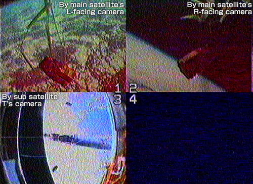
| Figure
2. Images just after sub satellite release |
Fig. 2 shows camera images down-linked
by Ku telemetry. Image No. 1 was taken by the main satellite’s L-facing
camera, No. 2 by its R-facing camera, and No. 3 by sub satellite T’s camera.
The photographs show the status just after release of the sub satellites from
the main satellite, and prove that separation was normal and mesh deployment
had just started. In image No. 3, we can see the main and L and R sub satellites
separating the main satellite against the earth. With these images and gyro
data, we confirmed previously that the main satellite’s wheel had functioned
normally to stop the rotation of the entire experiment system.
|
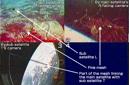
| Figure
3. Images just before the completion of mesh deployment |
Straws were used to house the mesh, which was an idea to
prevent raveling and high resistance at deployment. Based on the images and
data from accelerometers, we judge that there was little deceleration of all
three sub satellites by friction resistance on mesh deployment, and that they
reached their maximum distance 10m from the main satellite about 8sec after
separation. At that time, it is likely that mesh deployment to an equilateral
triangle with sides of around 17m was completed. Fig. 3 shows the images just
before completion of deployment. The main satellite’s L- and R-facing cameras
shot the fine mesh provided for the on-the-mesh moving system, which was pulled
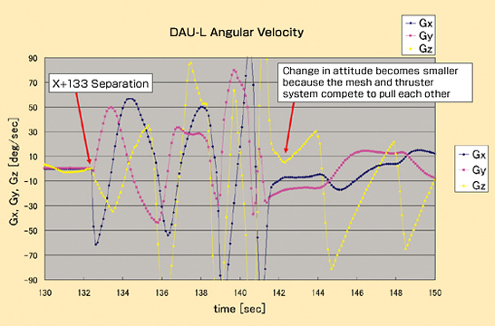
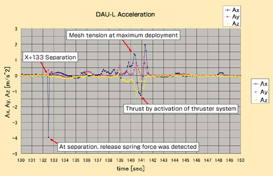
out during the final stage. Fig. 4 shows the records of sub satellite L’s
angular velocity and acceleration. Apart from the main satellite’s wheel
axis (Gz), two-axis coupled-rotation motion is visible. We can discern that
the motion was gradually interrupted by disturbances from the mesh. From the
acceleration records, we can see resistance forces caused by friction during
deployment, etc., the reactive force of the mesh reaching maximum extension,
and thruster-system control to prevent bound back. Based on telemetry data,
we are now creating a detailed analysis of 3D position, velocity and attitude.
We will examine the dynamics and control of the sub satellites as soon as the
analysis is complete.
|
| Figure
4. Profile of angular velocity and acceleration of sub satellite L |
|
|