


TOP > Report & Column > The Forefront of Space Science > 2008 > New Antennas to Support a Variety of Scientific Observation Missions:Key Communication Equipment Capable of Withstanding a Harsh Environment
![]()

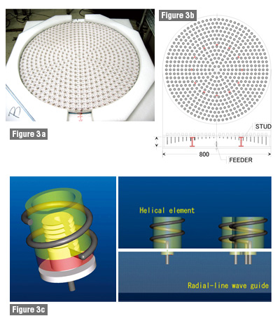
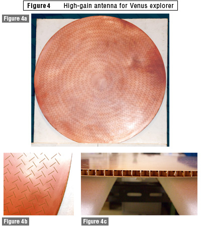
Wafer-like light antenna with high heat resistance Because planetary explorers perform far-distant communication over 1AU, a high-gain antenna by narrowing beam is required. In the past, parabolic antennas were used since they can converge radiowaves to a focal point on the antenna. For inner planetary explorers to visit Mercury or Venus, however, focal-structure antennas are unsuitable because they converge strong sunlight as well. We considered how we could develop and install planar antennas, completely different from traditional types, for such missions. Even if the antenna itself is small, there is a way to increase gain. If we array many antennas appropriately on the plane and align each ones feeder power and phase, the antenna gain would increase in proportion to the number of antennas. Even if the gain of one is only 9dBi, it is possible to obtain a high gain of 36.4dBi by arraying 546 elements. One more key factor in creating highly efficient antenna is how to reduce loss in circuits to feed power to individual elements. In typical array antennas, loss in feed circuits is high making them inefficient. The antenna we developed employs a feeding system with a wave-guide tube structure as shown in Fig. 3. The radio wave is emitted into the wave-guide tubes from the feeder pin in the center of the antennas reverse side and is fed to each antenna element by electromagnetic coupling. Therefore, loss becomes unboundedly zero and, by unifying feed distribution among the elements, we were able to realize a very high aperture-efficiency antenna.
The antenna is an electrical circuit but an unusual one. It has a 3D-spatial structure and its property is largely affected by its shape. In this regard, research and development in collaboration with rapidly advancing structural and material research is highly anticipated. In addition, if we achieve downsizing as well as lightweight, high-reliability and low-loss feed circuits by introducing the latest remarkable advances in microwave circuit research, it may be possible for us to install active phased-array antennas on explorers, of which direction and beam width can be freely and flexibly changed by control of the feeding amplitude and phase. A variety of antennas suitable for project-specific environments must be proposed in the future. One feature of the antenna is its diversity, so it is very possible that new antenna technologies will be created that respond to and suit newly emerging space projects. Yukio KAMATA |
| | 1 | 2 | 3 | |