
Materials Engineer = Merchant of Death?
There is a Japanese saying that there are people who ride the mikoshi (the portable shrine), who carry the mikoshi, as well as those who make straw sandals (meaning that there are many people of different roles and occupations that make the society). One of the authors, as a materials engineer in ISAS, may be described as those who soften the straw behind the astronomers who conduct observations on the mikoshi (scientific satellites), the system engineers who carry the mikoshi and the structural engineers who make straw sandals (launch vehicles).
The job of materials engineers is, originally, developing novel, light and strong materials. However, developing novel materials costs too much time to meet the schedule of space science projects. On the other hand, materials of the spacecraft are often used under extreme conditions; it makes it important to evaluate the features of the materials under the unique conditions of spacecrafts. Additionally, we are required to see whether those materials can stay robust without deteriorating under such harsh conditions through evaluating the reliability of the materials and structures nondestructively.
Ironically, the history has been repeated that when space projects suffer big failures, attentions are paid on materials and quality assurance and budgets are made for the materials field so that researches and developments are accelerated, while there comes a cost reduction after many successes have been made. Formerly in the 1979--1980, it was after the successive failures of the experimental geostationary communication satellite, Ayame 1 and 2, when radiographic testing technology for the propellants of the solid rocket motors (*1) was developed and the large X-ray computed tomography equipment was installed in the Tanegashima Space Center. And it was after the almost successive launch failures of H-II-5, -8, M-V-4, and H-IIA-6 during 1998--2003, when deficiency in material data storage and nondestructive inspection were strongly pointed out. After the M-V-4 failure, the researches on the ultrasonic testing of graphite material were promoted to accomplish the official standards (JIS Z 2356 and ISO 10830) and the advanced array-type ultrasonic testing system. After the H-IIA-6 failure, we developed the ultrasonic testing equipment for thick components of composite materials. After the H-II-8 failure, which collected a large social attention, we have started to create the engine-related materials database with a cooperation of National Institute for Materials Science.
(*1) Solid rocket motor: Rockets are divided into solid-propellant rockets and liquid-fuel rockets. The kick motors of Ayame 1 and 2, the first stage motor of M-V-4 and the SRB-A of H-IIA-6 belong to the former while the second stage engine of H-II-5 and the first stage engine of H-II-8 belong to the later.
As a party concerned, we are not intending to play the role of the merchants of death, but we would like to appeal strongly the importance of continuous researches and developments of basic material data storage and nondestructive inspection and evaluation. In that sense, the agreement on the collaborative research on nondestructive evaluation by National Institute of Materials (NIMS), National Institute of Advanced Industrial Science and Technology (AIST) and Japan Aerospace Exploration Agency (JAXA) is very meaningful for continuous researches and developments (Figure 1). With this agreement, in the JAXA projects join the technical groups in ALL-JAPAN beyond ALL-JAXA, and on the other hand NIMS and AIST are assisted to cross over the Death Valley between development and industrialization.
In this paper, we are going to give brief introductions on the recent achievements on the material degradation, residual life assessment and nondestructive inspection of the combustion chamber wall of the liquid rocket engine conducted within the framework.
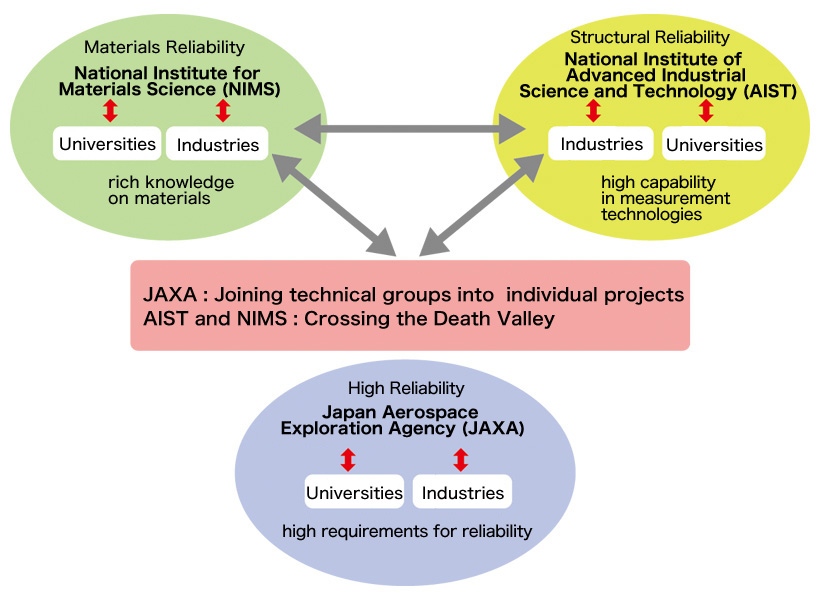
Figure 1. Collaborative research among National Institute for Materials Science (NIMS), National Institute of Advanced Industrial Science and Technology (AIST) and Japan Aerospace Exploration Agency (JAXA).
Creep-fatigue Damage of the Combustion Chamber Wall of the Liquid Rocket Engines
JAXA has been developing LE-9 engine for H3 Rocket, in which high reliability and extremely low costs are required (Figure 2 Left). Its combustion chamber has a double shell structure consisting of the inner cylinder made of the copper (Cu)-chromium (Cr)- zirconium (Zr) alloy and the outer cylinder heat resistant nickel alloy (Figure 2 Middle). The inner cylinder possesses cooling grooves for liquid hydrogen (LH2); the groove wall is exposed to the 3000°C burning gas and the -250°C LH2, and there happen large temperature changes and excessive thermal strain at start-up and shut-down processes. We have an experience that during the past ground firing tests of other engines, after around 20 combustion cycles, cracks were found on the LH2 side of the cooling groove (Figure 2 Right). Even the current, non-reusable rockets take flights with execution of several firing tests after engine fabrication, require crack detection, material degradation mechanism and residual life assessment indispensable for ensuring their reliability.

Figure 2. Liquid rocket engine (left), schematic of the combustion chamber (middle) and crack at the combustion chamber wall (right).
The Engineering Digital Innovation Center of JAXA conducted three-dimensional finite element analysis around the crack on the combustion chamber wall (Figure 3 Left). It was found that just after start-up the temperature of the combustion chamber rises rapidly to nearly 500°C, followed by the 270 s stable combustion and then the temperature drops rapidly after shut-down. With this process, the chamber wall would suffer from the compressive deformation and tensile deformation reaching the plastic region (*2) during the start-up and shut-down processes, and the extremely low speed tensile deformation (metallurgically similar to the tensile creep deformation) due to the slowly rising temperature of the outer cylinder during the stable combustion.
Troubles are used to be reported in the power-plant pipes caused by creep-fatigue, (*3) but the fatigue amplitudes of those case do not reach the plastic region. Under the condition of rocket engine which possesses both large plastic strain in fatigue mode and creep strain in creep mode, the material fails within less than 20 cycles in the creep-fatigue test (Figure 3 Right). In the creep-fatigue test, the material fails within the lifetime shorter than 1/10 of that in the simple creep test and within the life-cycles smaller than half of that in the simple fatigue test. It means that the simple linear cumulative rule does not effective at all.
(*2) Plastic region: When a force is applied to a metallic material, at first it shows only elastic deformation, but from a certain time, plastic deformation takes place.
(*3) Creep-fatigue: Among the loads that materials used to receive under high temperature, those that include creep phenomenon during cyclic deformation are called creep-fatigue, and they are one of the main reasons of material degradation in power plants.
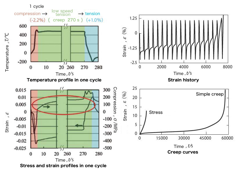
Figure 3. Load of the combustion chamber wall during one combustion cycle (left) and the result of the creep-fatigue test (right).
We observed the inside of the material during the creep-fatigue test to find the accumulation of the damages both in the creep mode (grain boundary voids) and the fatigue mode (fatigue cracks). The damage accumulation in creep-fatigue is understand as follows: the fatigue cracks are generated on the sample surface and develop toward the inside of the material through the grain boundary, on the other hand, the grain boundary voids are generated and grow in the inside of the material during creep, and finally the both damages join and causes rapid acceleration of material degradation.
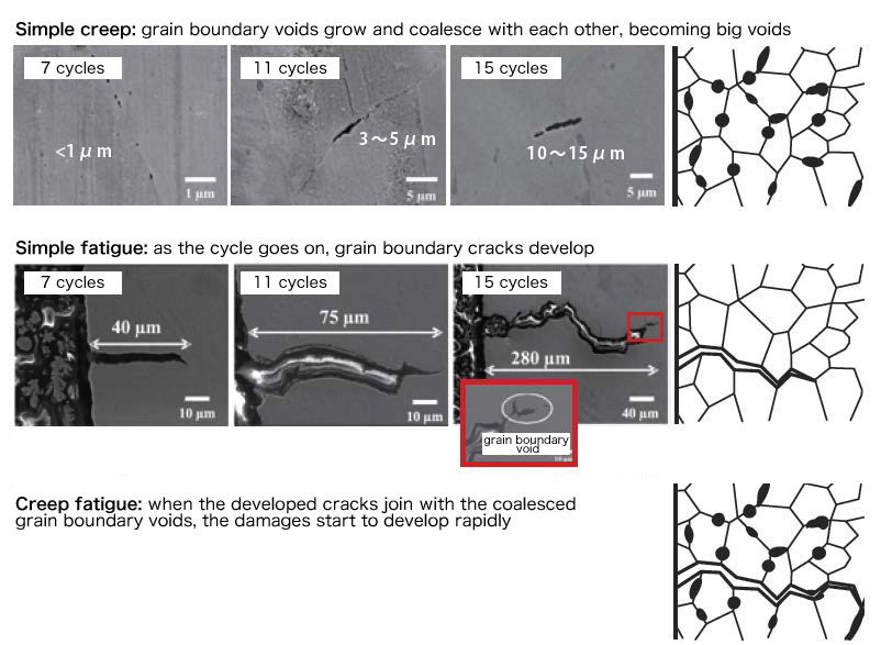
Figure 4. Damage propagation process in the combustion chamber wall during creep-fatigue.
Nondestructive Inspection and Residual Life Assessment of the Combustion Chamber Wall
Since the damage accumulation caused by creep-fatigue on the combustion chamber wall is not able to be avoided, we have to quantitatively measure and evaluate the damage of each combustion cycle with nondestructive methods. If we stop using the engine when a sub-millimeter-order crack, which indicates the final stage of the creep-fatigue, is detected, we can prevent big accidents. Additionally, if we are able to inspect the growth of the grain boundary voids less than the sub-micrometer level at earlier stages, we can evaluate the remaining use cycles (residual life) of the engine.
As for the nondestructive inspection of the cracks, since the combustion chamber wall possesses cooling grooves, the flow echo from the reverse side (LH2 side) detected on the inspection surface (combustion gas side) is buried under the shape echo of the cooling grooves. Currently we are examining considering nonlinear ultrasonic testing technique as well as the laser ultrasonic visualization technique. Especially the former, nonlinear ultrasonic testing technique can detect the waveform distortion in higher harmonic regions reflected by abnormal parts inside the material when they are shaken to large amplitudes by a burst wave. Since it does not utilize the acoustic impedance difference, the signals are not buried under the shape echo, we hope it can successively detect sub-micrometer cracks on the reverse side.
As for the residual life assessment, since it is necessary to inspect the grain boundary voids and micro-cracks under the sub-micrometer level, it is extremely difficult. Currently, we have just started collaborative research on the positron annihilation method and the electromagnetic inspection together with specialists from universities of our country.
Through the study of this special creep-fatigue phenomenon, we have become able to develop a rocket engine of the next generation launch vehicle with high reliability in designing with the basis of the damage accumulation mechanism. In addition, the nondestructive inspection of cracks and the residual life assessment of damage accumulation are not only necessary to improve the safety and reliability of the engine, but also an essential breakthrough to realize the reusable engines in the future. We should try our best to put them into practice.
(Eiichi Sato, Shusuke Hori)
ISAS News: September 2015 issue