


TOP > Report & Column > The Forefront of Space Science > 2014 > Honeycomb-structured Weight-saving High Gain Planar Antennas Installed on Hayabusa 2
![]()

Application to a small satellite for synthetic aperture radar system We are doing joint research with Prof. Hirobumi Saito, professor of ISAS spacecraft applied engineering research to apply the parallel-plate slot array antenna of honeycomb structure to the synthetic aperture radar system that can be mounted on 100kg class of small satellite. This research will be used for a disaster observation and maritime surveillance to perform the high frequency observed within a few hours. Since a short period of time visibility of the target exposed to the surface of the earth would be required for these main purpose, high-frequency observation band (9.65GHz) of X-band with strong straightness is appropriate. Furthermore, transmitting and receiving radio waves having a frequency width of 130MHz around the 9.65GHz are needed to get a resolution of about 3m required for visibility of artifacts. Additionally, in order to realize the 100kg class of small satellite at low cost, it is appropriate way to equip with all of the electronic device of the radar system in the satellite and expand only the planar antenna that is not mounted with electronics and formed it on the track. Figure 3 (a) shows the satellite external view. The antenna is composed from six 0.7m square panel and is housed in 0.7m3 size that piggyback launch is possible. It becomes 4.6m × 0.7m at the time of deployment. Solar panels are provided in the opposite side of the antenna. 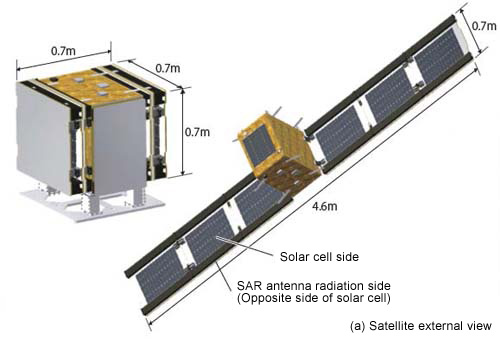
Figure 3 (b) shows the structure diagram of the antenna panel. A parallel plate waveguide is formed by putting the aluminum skin on both sides of the honeycomb structure of 0.7m square. A bottom is radiating surface, and the slot pairs are arranged that emits circularly polarized wave in a grid pattern on it. According to the incident direction of the radio waves of the slot pairs in the waveguide, the direction of rotation of the circularly polarized waves can be changed. Therefore, the structure is designed that the radio waves incident from two directions into the slot pair by providing a feed waveguide at both ends of the upper surface in order to emit a right-handed circular polarization and left circular polarization from each. Feed waveguide consists of two types. The outside of it powers the radio waves to the inside of the panel as described above, and the inside do branch feeding the radio waves to six panels. In order to have the same line length for each panel, every lengths of feed waveguides between panels are equal in any path like the figure of the sports event of the tournament. We'll explain the operating principle. Radio waves propagate from the power feeding window that is opened in the narrow walls of the panel between the feed waveguide to the panel in the feed waveguide. Next, the waves propagate through coupling slot that has been opened in the wide wall of the panel in the feed waveguide to the parallel plate waveguide. And finally, the waves are radiated as circularly polarized wave from slot pairs on the parallel plate waveguide. 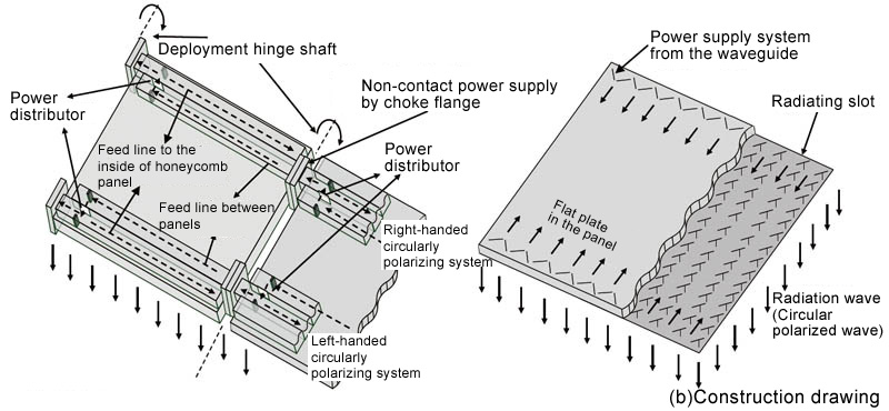
To confirm the operation, we designed a right-hand circularly polarized antenna panel (0.7m square) provided the feed waveguide on only one end of the upper side of the parallel plate waveguide, made a prototype product of and evaluated. Using an aramid fiber sheet as a honeycomb core material, its thickness is 6mm. The gain 35.0dBi is obtained, and antenna efficiency is 55%. It is similar with the gain of a circular antenna of "Hayabusa 2". The loss is 1.6dB, and 0.8dB is considered to be due to the honeycomb core. The rest of 0.8dB is considered to be due to electrically-conductive adhesive that was used to fix the feed waveguide to the parallel-plate waveguide and fasten the periphery of the parallel-plate waveguide by metal channel. This rectangular antenna has the feature that it can be folded and deployed as folding screen like the solar panels. Since it can be stored easily, as shown in figure 3, and installed on the 0.7m3 small satellite, as well as launched and deployed in orbit, we believe that the day is coming that small satellites equipped with radar make great achievements. 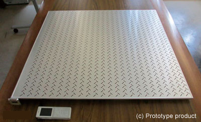
Closing remarks We explained the high-gain flat antenna that was lighter by the honeycomb structure for being spaceborne. In the future, in addition to the use of more low-loss honeycomb core material, it is necessary to consider the characteristics improvement by electromagnetic field analysis of the antenna captured a honeycomb structure accurately. (Jiro Hirokawa)
|
||||||||||||||