


TOP > Report & Column > The Forefront of Space Science > 2014 > Honeycomb-structured Weight-saving High Gain Planar Antennas Installed on Hayabusa 2
![]()

Radial Line Slot Antennas In Figure 2, we show a photo and structural diagram of a radial line slot antenna, which is used as mounted high-gain planar antenna of "Hayabusa 2". Radial line slot antenna was invented by Prof. Goto Naohisa, professor emeritus of Tokyo Institute of Technology, and has been put to practical use as a high-efficiency planar antenna for satellite broadcast reception. The two circular conductive plates are simply inserted through the dielectric and constitute a radial line, and input a signal transmitted as a radio wave to the antenna by a coaxial line provided at its center. Radio waves powered from a coaxial line are radiated from the slot, a number of narrow window drilled in the upper circular conductor plate, to the outside while propagating through the radial line as cylindrical waves of outward. In the telecommunications sector, the radio wave whose direction of the electric field rotates with time (called as the circular polarized wave) is suitable in that the satellite can communicate stably even though its position changes. Setting two orthogonal linear slots staggered by 1/4 of wavelength (called the slot pair), circularly polarized wave will occur like the principle that circular motion occurs by applying a single vibration of the phase difference of 90 degrees to the X-axis and Y-axis. Additionally, the slot pair are arranged in a spiral for radiating a radio wave toward the front direction. There are approximately 15,000 slots pairs installed on the antenna, and in order to control the waves of the amplitude and phase of the emission from each pair, the length of each slot is varied slightly apart. 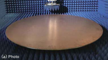 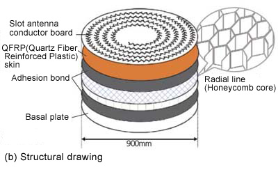
Radial line slot antenna with honeycomb structure In order to reduce weight of the radial line slot antenna for the satellite, a radial line was achieved with the honeycomb structure shown in Figure 2 (b). Under the guidance of Prof. Makoto Ando, professor of Tokyo Institute of Technology, we designed it, made a prototype product of and evaluated with the cooperation of NEC TOSHIBA Space Systems, Ltd. Firstly, we have designed the X-band antenna at 8.4GHz. In the actual antenna, waveguide forms honeycomb structure, and thousands of slot pair is provided spirally on a circular conductor plate. It is too difficult to analyze and design the antenna with taking these into account with accuracy. For this reason, some approximation were introduced. Spiral-shaped array of slot pair is usually greater curvature toward the outer circumference of the disc, but the array was replaced with a grid-like array in disregard of this curvature under our analysis. In addition, we hypothesize the periodicity of the electromagnetic field in the transverse direction and have introduced a one-dimensional array model that extract only the direction of travel of the radio waves. Also, since it is difficult to take into account the hexagonal shape and thickness of the honeycomb core in the overall design of the antenna, a simple design model is required. A portion of the honeycomb core of thickness 5mm was replaced with dielectric layer of homogeneity of the relative dielectric constant 1.03 because hexagon of the period of the honeycomb core is 1/4 inch (6.35mm) and sufficiently small compared to the wavelength (35.69mm) at 8.4GHz. However, since the skin of thickness 0.36mm directly under the slot antenna affects the radiation characteristics of the slot antenna, we were taken into account it as a separate layer of the dielectric constant 3.10 in the design. The honeycomb core is made from a material called Quartz that transmission loss is small. It was revealed in the experiment that transmission loss of the waveguide of the honeycomb structure was the only 0.03dB per 1cm. The antenna with a diameter of 92cm is as light as only 1.16kg, and the gain was 35.9dBi and the efficiency of the antennas was 58.7%. We compared it with the parabolic antenna with a diameter of 1.6m, which is mounted in the "Hayabusa". The gain of parabolic antenna of "Hayabusa" is 37.0dB, and the weight is 6.8kg. In the planar antenna of "Hayabusa 2", its gain is 22% lower (1.1dB reduction) than Hayabusa, but its weight is lightened by 83%. Then we designed the Ka-band antenna at 32.0GHz. First, we measured the electromagnetic field distribution in the waveguide by the honeycomb core of 1/4 inch period like the case of the X-band antenna. As the result of it, amplitude distribution of the hexagon that is believed to be due to the hexagonal shape of the honeycomb core has been observed in a circumferential direction. This was thought to result from that the wavelength at 32.0GHz decreased to 9.37mm, and the period of the honeycomb core is too large in 1/4 inch (6.35mm). Therefore, the period of the honeycomb core was reduced to 1/8 inch (3.17mm). However, at that time, Nomex (R) what is larger transmission loss as compared to Quartz was only available as the honeycomb core material of 1/8 inch period. Therefore, the transmission loss of the waveguide of the honeycomb structure raised to 0.16dB per 1cm. Although we was able to achieve the gain of 44.6dBi in the antenna with a diameter of 90cm, there was also the loss of 3.7dB, many of which are considered to be due to the honeycomb core.
|
||||||