Radio Info
latest news (11/22 10:30 UTC)
English
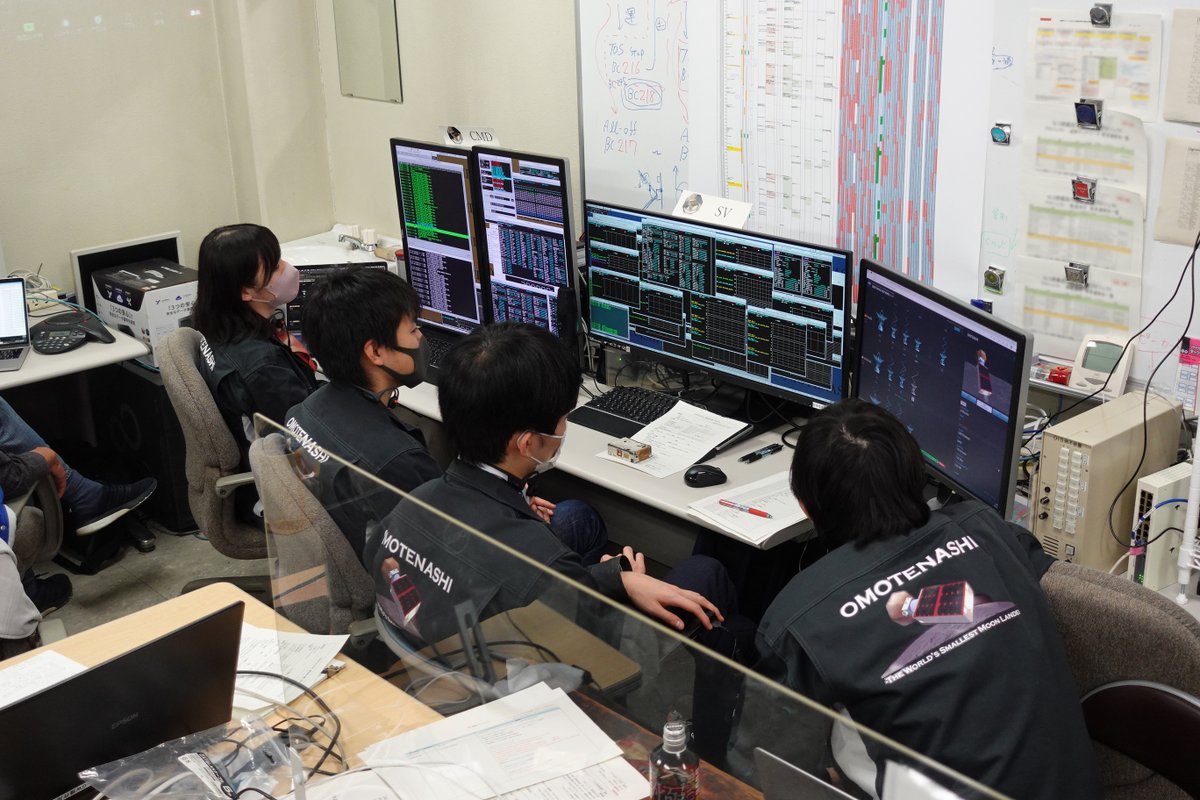
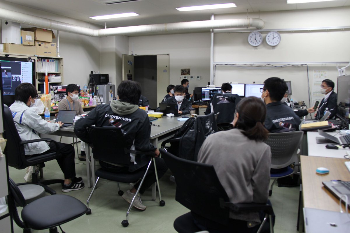
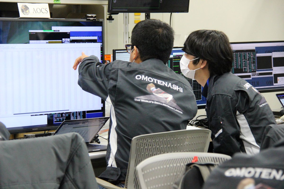
We got pictures when we operated OMOTENASHI with the last chance for the Moon landing. (Operation Room) Fig.2 shows our Project Room at the same. OMOTENASHI flew by the Moon and will escape from the gravity area of the Earth after approaching the Earth once. We will halt searching for a while as the orbital error becomes more significant, and the Sun is not direct to the spacecraft in this orbit. We will investigate the cause of what we faced and analyze the data obtained from OMOTENASHI. Suppose that the axis of rotation is stable; the spacecraft will get sunlight when the direction of the Sun changes. We anticipate this situation will occur in March next year. Then we will restart the search operation again and start capable technical demonstrations if we can connect between OMOTENASHI. For this operation, we discuss with related associations. As the distance increases, the search region will narrow as the angular error gets smaller, though the link margin is weak. Restarting in March is good in this respect on this point, too. The ultra-small CubeSats must be essential tools for space development from now on. Therefore we want to demonstrate as many as one equipped technologies by restoring OMOTENASHI.日本語
今朝の月着陸ラストチャンス運用の写真が届いたので共有します。1枚目は運用室の様子,2枚目はその時のOMOTENASHIプロジェクト室の様子です。 OMOTENASHIは月をフライバイし、一度地球に近づいてから地球重力圏から脱出する軌道に入っています。月フライバイ後の軌道では、軌道誤差が大きくなり探索範囲が広くなること、太陽光条件がしばらく改善しないであろうことから、当面、探査機運用はお休みします。 今後、プロジェクトチームは、起こった事象の原因究明と軌道上で得られたデータの解析を中心に行っていきます。 宇宙空間での探査機の回転軸方向が一定だとすると、探査機から見た太陽方向が変われば、太陽電池に光があたるようになります。来年3月頃から太陽電池が徐々に太陽側を向くと予想されます。 そのころから探索運用を再開し、探査機と通信が確立したら、軌道上でできる試験項目を実施していきたいと考えていますが、今後の対応については、関係各所と相談しながらすすめていきます 距離が遠くなると通信条件は悪くなりますが、軌道誤差があっても角度誤差は小さくなるので、アンテナでの探索範囲は狭まります。その点でも、3月以降が適切だと考えています。 超小型探査機は今後の宇宙開発に重要な手段だと考えています。超小型探査技術の発展に役立てるように、探査機の復旧をして、一つでも多くの技術試験を実施したいと考えています。latest news (11/21 00:10UTC)
English
Thank you for your supports. Unfortunately, we have yet to receive signals from OMOTENASHI. The orbit was not so different from it separated from the rocket. However, there is a possibility its orbit has some errors, and we did search operations by deviating JAXA's antennas. Although we first planned to operate with the UDSC64M antenna, we exchanged the antenna with the EQUULEUS team as the USC34M antenna has a broader beam. Now we cannot execute pre-established landing sequences. But if we recover our spacecraft in a day, it is possible to fire and deaccelerate the Solid Rocket Motor and let OMOTENASHI land on the Moon in free fall at perilune. The time of passing that point is at about 24:00 on 11/21 JST. Therefore, we prepared command files to establish three axes attitudes control, pre-sequences for landing, and landing sequences. We confirmed these commands worked fine with the simulator of OMOTENASHI yesterday. Tonight is the last chance to land on the Moon, and we continue our landing mission.日本語
みなさま、応援ありがとうございます。残念ながら、現在、探査機からの電波は受信できていません。 探査機の軌道はロケットから分離時とほぼ変わっていないと想定されますが、もしも軌道がずれていて受信できない可能性も考えて、アンテナ方向を動かして探索する運用も行いました。 また、臼田局64mアンテナでの運用を予定していたのですが、アンテナビーム幅がより広い内之浦局34mアンテナを使用するため、EQUULEUSと運用局を交換しました。 現時点では、当初予定していた着陸方法は実行できないのですが、本日中に回復できれば、近月点(月に最も近いところ)を通過する際に固体ロケットで減速して、月面に自由落下させることができます。 近月点通過は、日本時間の今晩、24時付近です。 そのため、電波受信ができたら素早く3軸姿勢制御確立、着陸のための準備、着陸シーケンス送信する手順を確認し、コマンドファイルを用意しました。 また昨日、この手順で問題無いかどうか、探査機シミュレータを使って運用リハーサルを行いました。NASA DSN局にも、この時間の運用パスを確保してもらっています。 今日の夜中までが月面着陸についてはラストチャンスになります。長期戦になる覚悟も必要ですが、今晩までは着陸について万全の準備をしていきます。latest news (11/17 09:20UTC)
English
The following is the latest report from OMOTENASHI team leader: Hashimoto Tatsuaki. After separation from the SLS, as the radio signal from the CubeSat was unstable, it was challenging to get telemetry from NASA's Deep Space Network station in Madrid. When we finally found and locked the signal from OMOTENASHI, we got to know the Solar Cells faced away from the Sun and the CubeSat was rotating fast. For these reasons, we decided to use the propulsion system to stop its spin rather than attempt to direct Solar Cells to the Sun with the attitude control system. After that, we switched operations from stopping spin to changing the spin axis to obtain solar direction because of the dropping battery voltage. However, the battery power was gone, and its RF transmission stopped when the operation from Madrid ended. Still, now, its communication has yet to recover.We developed OMOTENASHI over six years, and we did a lot of tests and training. We think no components on OMOTENASHI are broken, so we determined to keep the operation: recover OMOTENASHI's attitude power and complete our mission.
日本語
OMOTENASHIチーム長の橋本です。 ロケットから分離後、探査機からの電波が安定せずNASA DSNマドリード局ではなかなかテレメトリがロックしませんでした。 ようやくロックさせて状態を確認すると、太陽電池が太陽と反対方向を向き、探査機は速い回転をしていました。 そのため、姿勢制御により太陽電池を太陽方向に向けるのではなく、ガスジェット装置を使って回転を停めることにしました。 太陽電池での発電がなくバッテリー電圧が低下し続けたことを考え、回転を停める操作から変更し、回転軸方向を変えて太陽電池が太陽に向くようにガスジェットを噴射しました。 しかしマドリード局の最後では電圧不足から送信機はオフ。その後現在まで送信電波は復帰していません。 OMOTENASHIは6年の歳月をかけてインハウスで開発してきました。 現状、故障している機器はないと思われるので、なんとしても姿勢回復して、ミッションを達成したいと考えています。Orbiting Module
DOWNLINK
- Frequency
- 437.31MHz
- Antenna
- SRR antenna
- Polarization
- Linear
- Modulation
- beacon, PSK31
- Sync Word
- C1 (ASCII code)
- Power
- 30dBm
UPLINK
- Frequency
- UHF-band
- Antenna
- 12M dish
- Polarization
- LHCP, RHCP
- Modulation
- FSK
- Sync Word
- FAF320
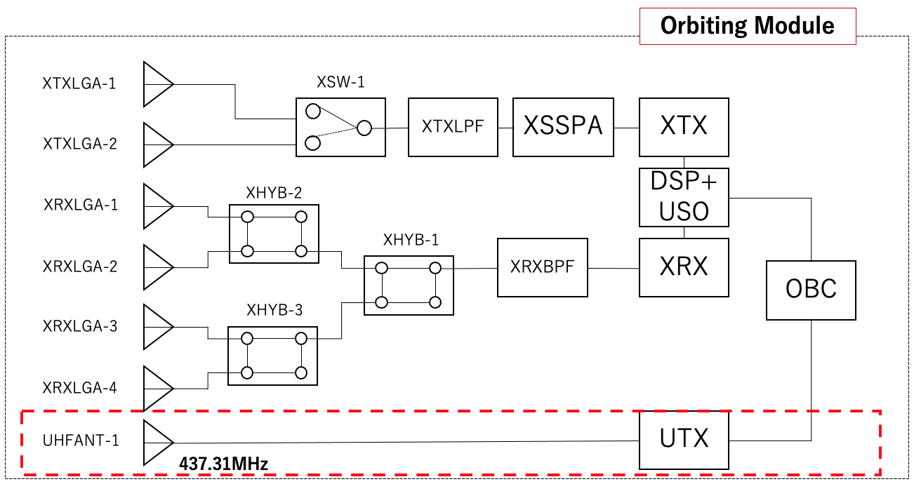
The diagram of communication system (OM)
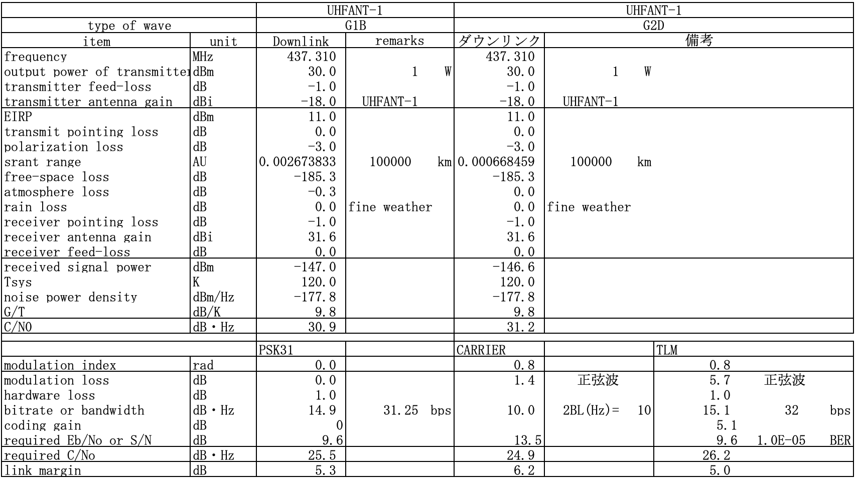
Link Budget PSK31 & PCM-PSK/PM from OM
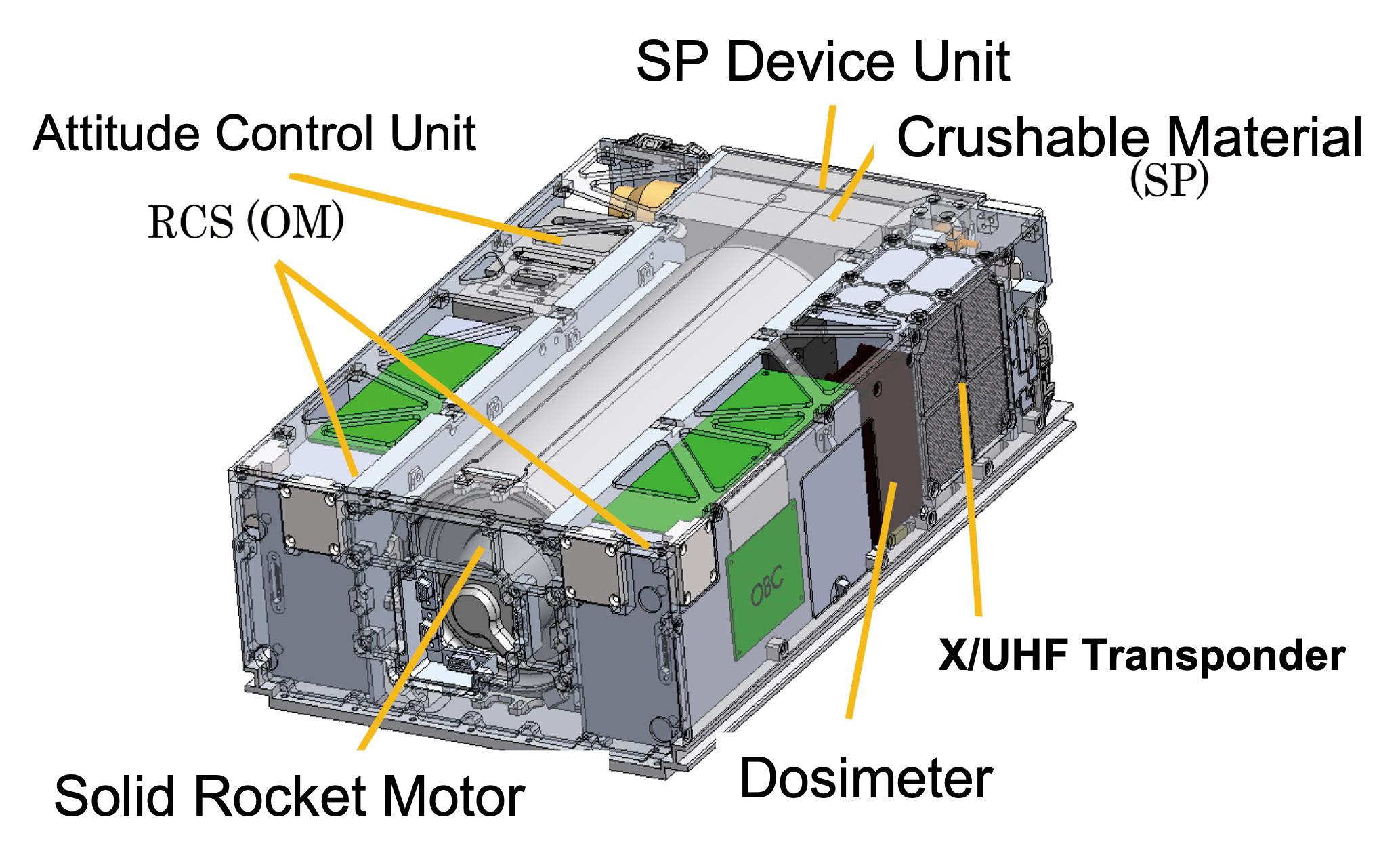
OMOTENASHI overview
OMOTENASHI is 6U CubeSat, and it composed of three parts: Orbintg Module(OM), Surface Probe(SP) and Solid Rocket Motor(SM). The function of Orbiting Module is to bring Surface Probe and Solid rocket Motor to the Lunar Impact Orbit. Next, the unique characteristic of OMOTENASHI is that; it has a solid rocket motor inside! (This cylindrical component is that. ) We have to design a solid rocket motor to decelerate the Moon lander on the landing phase. We put it vertically through the interior and arranged the other components on either side.At last, the square box on the head of a rocket motor is the moon lander, Surface Probe. As OMOTENASHI has no soft-landing mechanism(such as legs or parashoot), the light and tiny component only can land and survive on the Moon.
OMOTENASHI (Overview)
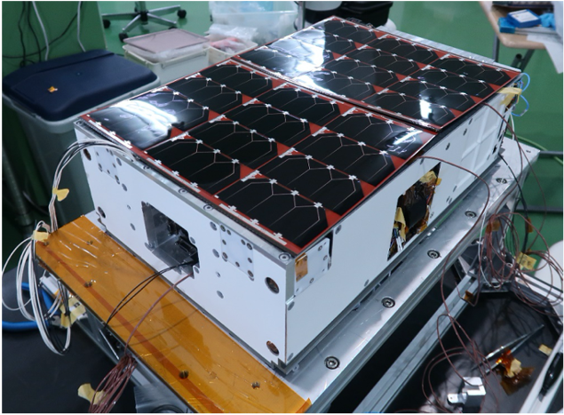
OMOTENASHI (FM)
 The communication systems work on X band and UHF band.
The X-band LGA is patch antenna and has about 7dBi. In UHF-band, we develop metamaterial antenna for the limited space.
As OMOTENASHI is 6U CubeSat, we don't use big connector such as DSub or SMA, and we apply tiny connectors instead, such as MDM or SMPM.
X Transponder and UHF TX/RX
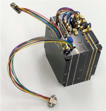
X Transponder and UHF TX/RX
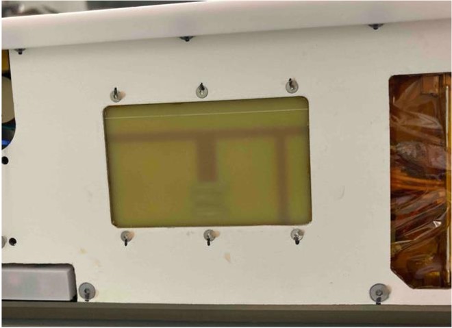
Suraface Probe
DOWNLINK
- Frequency
- 437.41MHz
- Antenna
- invert-F antennax4
- Polarization
- LHCP(, RHCP)
- Modulation
- FM, PSK31, PCM-PSK/PM
- Sync Word
- C1 (ASCII code)
- Power
- 30dBm
The diagram of communication system (SP)

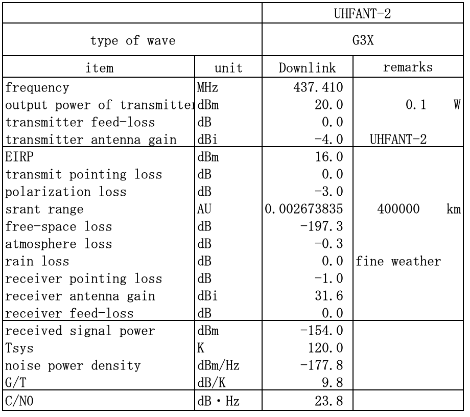
Link Budget PCM-PSK/PM from SP
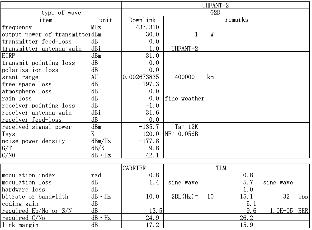
Link Budget for FM Modulation from SP
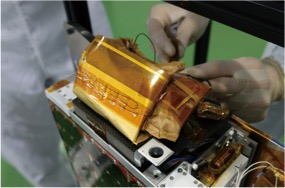
In the figure below, you can see Surface Probe in the center, and its shape is a rectangular box. The octagon clothes around the SP is an antenna in the UHF band. We array four invert-F antennas to generate circular polarized RF waves; they have a 90 degrees phase difference with the neighboring element. And the Surface Probe is filled with epoxy to endure the landing shock. We fold this antenna when stored in OM, as the last figure shows.
Surface Probe (Overview)
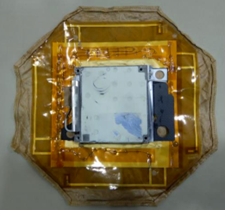
Surface Probe (Folded)
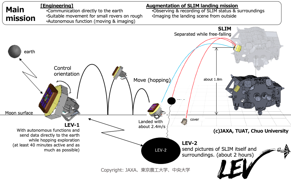
LEV Mission
- Communicattion directly to the earth
- Suitable movement for small rovers on rough
- Autonomous function (move&image)
- Observing & recording SLIM status & surroundings
- Imaging the landing scene from outside
for QSL: Please Send Us Info as Below;
- The screenshot proves your success recording the signal or telemetry data.
- The date and location(country) when you record.
- We could introduce you on our HP or SNS, if you could inform us your receiver equipment and the above.
Decode
We had planned to publish our decode table beforehand. However, we would like to confirm the receive-achiever, so please contact us if you could receive it.OMOTENASHI Mission
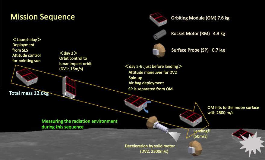
- Verification of the semi-hard landing with airbag and others
- Development of ultra-compact transponder and solid motor
- The trajectory design for robust horizontal landing baesd on precision orbit determination
- Measuring the radiation environment near the Earth and the Moon
The Operation of OM-Communication
It will transmit beacon or telemetry data with PSK31 in somewhere path on the way to the Moon.That antenna gain is too small, so it is not easy to receive telemetry data. JHRC sends everyone who succeeds in capturing the beacon or carrier signal.
Decode
Orbiting Module transmits in PSK31 mode in UHF-band. We had planned to publish our decode table beforehands, however, we canceled it to confrim receive-achiever certainly. So, if you did receive alphabet and numbers, please send us that characters. If you couldn't get any characters, please send us following data;[Please Send Us Info as Below;]
- The screenshot proves your success recording the signal or telemetry data.
- The date and location(country) when you record.
- We could introduce you on our HP or SNS, if you could inform us your receiver equipment and the above.
The Operation of SP-Communication
OM turns on the power of SP before separating from OM. Until landing on the Moon, SP emits radio waves with FM modulation by the 3-axis accelerometer in SP. In FM mode, it occupies about 100kHz bandwidth. After landing, the transmission mode is automatically switched to PCM-PSK/PM and sends the digital telemetry.[Please Send Us Info as Below;]
- FM mode: Please record the analog data in 100kHz bandwidth. Center frequency is 437.41MHz.
- PCM-PSK/PM: The screenshot proves your success recording the signal or telemetry data.
- The date and location(country) when you record.
- We could introduce you on our HP or SNS, if you could inform us your receiver equipment and the above.
OMOTENASHI Orbit Information
The launch was success on December 16,2022.
Liftoff! NASA’s Artemis I Mega Rocket Launches Orion to Moon
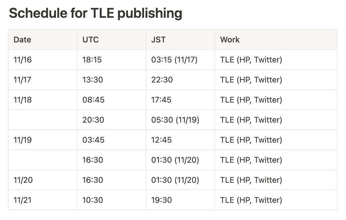
TLE Schedule
 Attention:
We operate OMOTENASHI with real-time commands, so this schedule is just a reference.
Of cource, it also depends on the actual launch time, as this schedule is for the case that SLS flies on the window open time.
Tools for JPL Horizon
These program can create POST request to JPL Horizon. To use Haskell code, you need next modules, http-conduit and bytestring.- python ... JPLHorizon_OMOTENASHI.py
- Haskell ... JPLHorizon.hs
The diagram of Ground Station (Wakayama & JHRC)
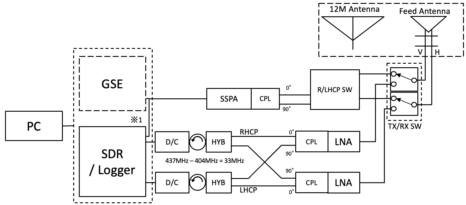
On the other hand, the SP antenna's polarization is normally RHCP when SP lands with the electrical box facing down on the Moon. Thus, we combine the V and H signals with 90 degrees phase difference.
However, depending on terrain factors and others, we can't rule out the electrical box's possibility of facing up; this means SP's antenna is upside down and seems like LHCP from the Earth. Be prepared for this, our grand station has a polarization switch (R/LHCP SW in the Figure).
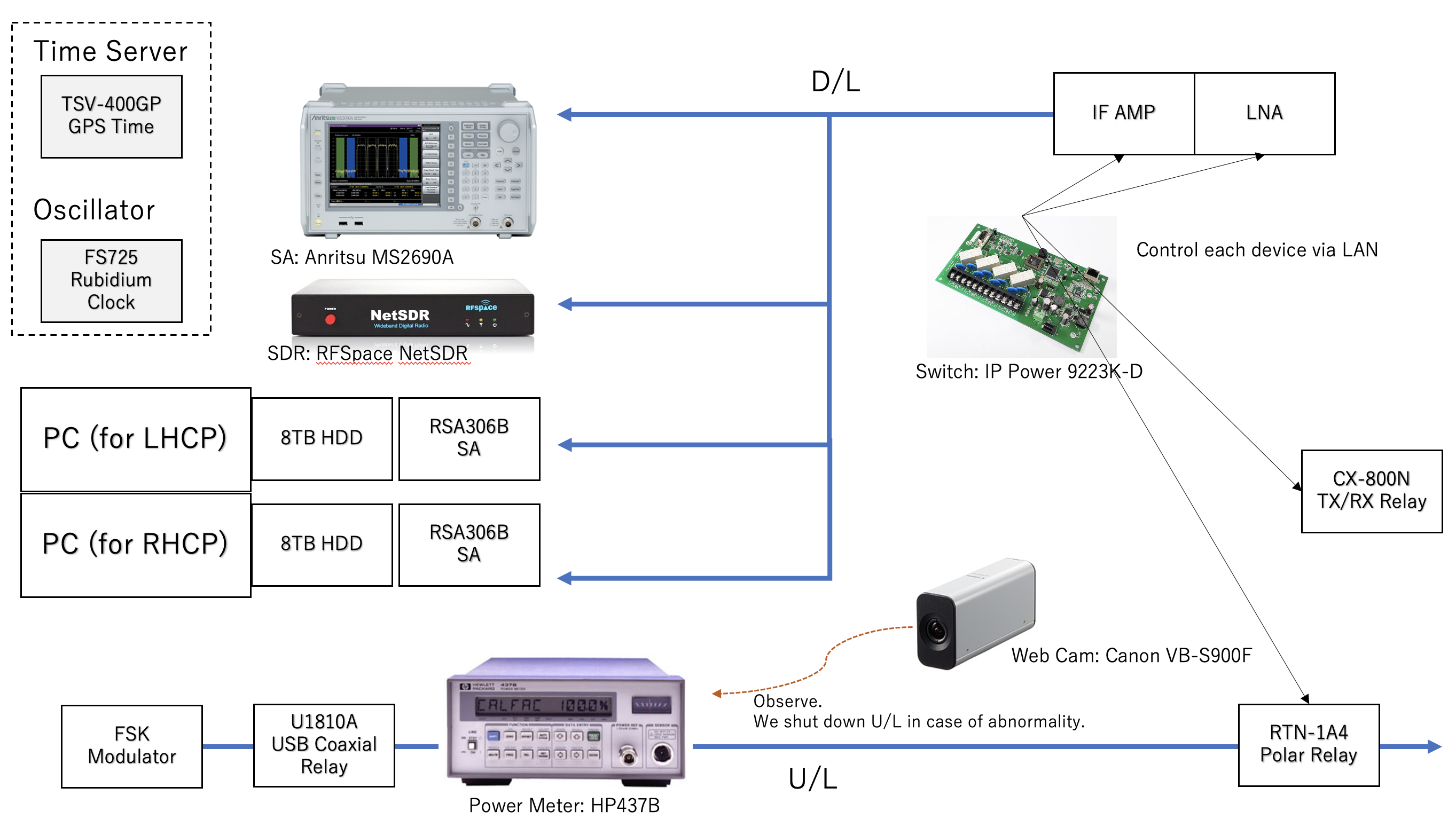
The Diagram of Ground System
XQuad Antenna

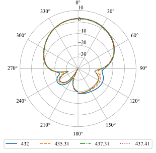
XQuad Antenna Pattern
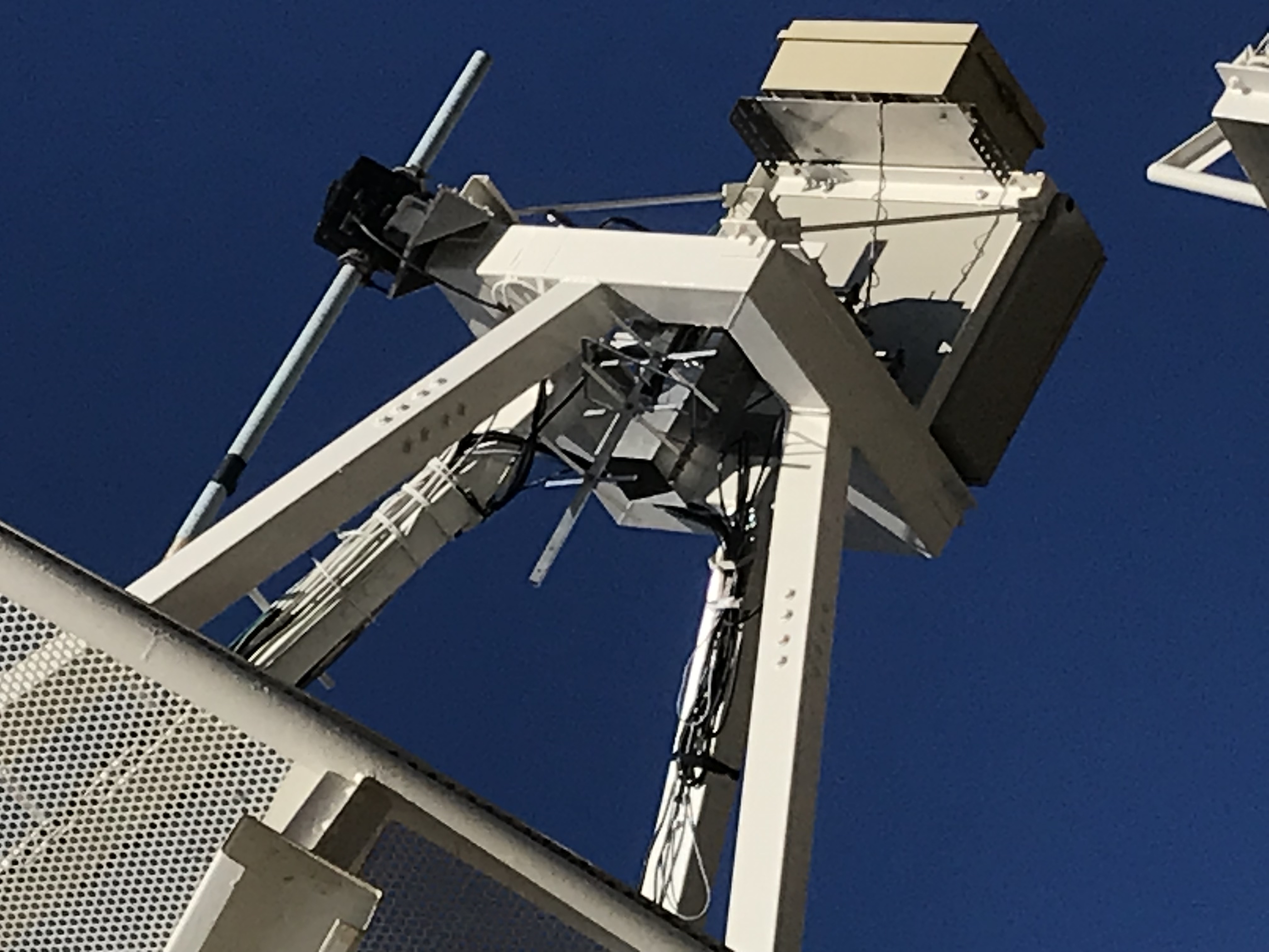
Equipped XQuad on Dish
Other Components
| Item | Product Num. | Manufacturer | Remarks |
|---|---|---|---|
| SDR | IC-9700 | ICOM | |
| TX/RX SW | CN-800N | TOHTSU | I/F: DPDT |
| R/LHCP SW | RCT RTL-TN1A4 | ||
| CPL | MODEL QH6258 | WERLATONE | |
| D/C | LOW NOISE XTAL OSCILLATOR | VHF Design | to downconvert to 33MHz |
| LNA | ZX60-P103LN+ | Mini-Circuits | Gain:20.3dB(500MHz) |
| Logger | RSA300Series (x2) | Tektronics |
SNS
Address [English]
- address: 252-5210 ISAS, Yoshinodai 3-1-1, Sagamihara-shi Chuo-ku, Kanagawa in Japan
- [Direct to JAXA Ham Radio Club] torii.wataru "at" jaxa.jp convert "at" to @ on sending mail
Address [Japanese]
- 住所: 252-5210 神奈川県相模原市中央区由野台3-1-1 宇宙科学研究所
- [JAXAアマチュア無線クラブ直通] torii.wataru "at" jaxa.jp "at"を@に置き換えてメールください
