


TOP > Report & Column > The Forefront of Space Science > 2014 > Removing the Carbon Dioxide Using Fuel Cells
![]()

Creating Electricity Using CO2 As mentioned above, although empirically the realization of reducing CO2 is difficult, it is easy theoretically. So we decided to entrust the reduction of CO2 to the fuel cells, a kind of power generator. Here, we'll explain a little bit about the fuel cells. Typical fuel cell is a device for generating power by supplying oxygen to the cathode or hydrogen to the anode. While conventional storage batteries encapsulate the reducing agent and oxidizing agent into a package, fuel cells use the oxidizing agent (oxygen) and reducing agent (hydrogen) supplied from outside. From this, a fuel cell can be said as a power generator that can continuously generates power when supplied with hydrogen and oxygen. The total reaction of hydrogen - oxygen fuel cells, which is the representative of the fuel cell, can be written as equation (3). H2+1/2O2=H2O+286kJE(3) The anode reaction is: H2→2H++2e-E(3.1) And the cathode reaction is: 1/2O2+2H++2e-→H2OE(3.2) In this fuel cell, theoretically, 83% of the heat of combustion can be efficiently converted into electrical energy (at 25℃), so on the ground it has been made practical in home use and automotive applications. Again, let us focus on the equation (2). We have produced hydrogen - carbon dioxide fuel cells based on this. The structure of the fuel cell is shown in Figure 1, but the main part is extremely thin and compact. This structure is classified as a polymer electrolyte fuel cell (PEFC). Figure 2 (left) is the conceptual diagram of the hydrogen - carbon dioxide fuel cells. We supply hydrogen to the anode, and the reaction is considered to be: 4H2→8H++8e-E(2.1) And when we supply CO2 to the cathode, the main reaction is considered to be: CO2+8H++8e-→CH4+2H2OE(2.2) 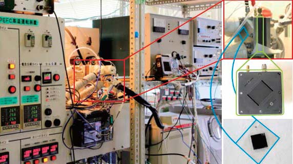
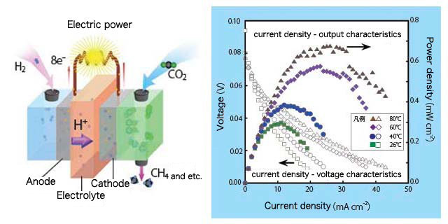
The results of the power generation tests done on the hydrogen-carbon dioxide fuel cell are shown in the graph in figure 2. The horizontal axis of the graph shows the current density between the positive electrode and the negative electrode, and the vertical axis on the left shows the voltage between the two electrodes while the vertical axis on the right shows the output power of the fuel cell. From the graph, obviously the fuel cell is generating power, and the power generation output depends on the temperature. In our research, it is the first time that the hydrogen-carbon dioxide fuel cell has been found to be able to generate electric power. This should be the consequence that the electrode material used in the experiment is working properly as an electrode catalyst. However there are also problems such as that there are many kinds of products other than CH4, the products adsorb strongly to the electrode, making it difficult to take them out, and so on. Currently, we are conducting out research focusing on these problems.
|
||||||||||