


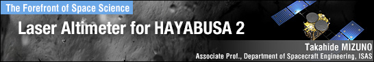
TOP > Report & Column > The Forefront of Space Science > 2013 > Laser Altimeter for HAYABUSA 2
![]()
Laser Next, the detection circuits for the laser and fine light intensity, a unique part of the laser altimeter, are explained. The laser used in the altimeter is 1.064?m wavelength light. To produce this light, the rod is prepared by applying neodymium (ND) ion of the light-emitting element to a crystal called Yttrium Aluminum Garnet (YAG). Laser light is generated when the Laser Diode (LD) light is absorbed by the rod. Fig. 2a is a photograph of the prototype model of the laser part used in HAYABUSA. Various devices are mounted on the 15cm-square base including the laser rod in between the emission mirror, which comprises resonator, Porro prism, trapezoidal prism, and Q switch for generating large short-pulse output. The red line shows the light path and the arrow shows the direction of the laser light emission. The Q switchs role is to instantaneously trigger short, strong pulse oscillation shortly after the energy absorbed in the YAG rod becomes sufficient. 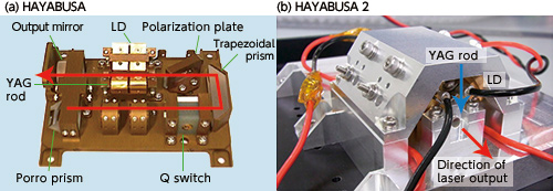
HAYABUSAs laser emission is short (15nano sec.) but strong (1Mega Watt). Regarding the Q switch, since we knew that it was vulnerable to temperature change in a vacuum environment, we started to design a replacement from the year after the HAYABUSA launch. The replacement was a laser using Cr4+ saturable absorber, developed in cooperation with a manufacturer. Fig. 2b shows the newly developed laser part prototype for HAYABUSA-2. The absorber acts as an energy absorber to a certain level of the energy in the YAG rod. As soon as the energy exceeds that level, however, the absorber suddenly stops energy absorption. This characteristic is utilized as a Q switch. The laser oscillator of HAYABUSA-2 comprises the YAG rod equipped with a thin plate of saturable absorber on one side and a mirror coated on its front and back. As a result, the new oscillator is stowed in a YAG rod of 3mm diameter and 40mm length. Compared to the former HAYABUSA laser part that was about 150mm square, the new laser part has been reduced to 50mm square. Of course, the laser is robust to temperature change in a vacuum environment. Detection of receiving light The next point is the detection of the subtle light returning from a target after reflection. Detection is performed by an APD that converts light to electric current, amplifier and timing-detection circuits. The amplifier, in particular, reflects the designers concept. Laser altimeter design requires technology to realize an optimal balance in detection sensitivity including laser output and receiving telescope. If the balance were lost, size and weight would increase. Furthermore, for planetary explorers, a short development period is sometimes required due to short launch period. HAYABUSA adopted an amplifier that utilizes a charge amp, which narrows signal bandwidth to constrain noise. Its circuit gain can adapt to changes in light density up to one million times. This becomes possible by switching the APD bias voltage and the amp feedback capacity and also, in extremely short distance, by utilizing the gap in field of view of the transmitting/receiving optical system. Fig. 3a shows the received light intensity and distance data measured by HAYABUSAs laser altimeter. This indicates that the receiving energy changed clearly in response to distance. Nonetheless, a great amount of time was spent adjusting the charge amp circuit in HAYABUSA.
|
||||||