


TOP > Report & Column > The Forefront of Space Science > 2008 > New Antennas to Support a Variety of Scientific Observation Missions:Key Communication Equipment Capable of Withstanding a Harsh Environment
![]()

Role and importance of antenna Observation data from satellites or explorers are sent to ground stations by radio waves propagated through the vacuum of outer space. Command codes from the ground are also carried by radio waves. The instrument to transmit and receive radio waves is the antenna, in other words, converting electrical signals to and from radio waves. In wireless communications, the antennas radiation property has a decisive effect on the quality of communications and, thus, is very important to the successful retrieval of observational data. The antenna is a passive device with no electric power consumption and no heat generation. Optimal design of the antenna system leads to optimal design and downsizing of spacecraft. Features of antenna for scientific observation spacecraft Low earth-orbiting satellites require omnidirectional antennas so that the communication link with the ground can be assured regardless of satellite attitude. The radiation properties of omnidirectional antennas, however, are affected by the spacecrafts structure. It is necessary therefore to consider the satellite structure as part of the antenna. Since satellite shapes are always changing, we focused on optimizing characteristics to meet individual requirements. Meanwhile, in the case of planetary explorers, the distance between the ground stations is sometimes over 1 AU (Astronomical Unit; about 150 million km, i.e., mean distance between the Earth and Sun). Radio signals spread out to become weak because the radio waves power density is inversely proportional to distance squared. Compared to geosynchronous satellites at an altitude of about 40,000 km, power density reduces 14 million times. To cope with these conditions, medium- to high-gain antennas with narrower directionality in radio radiation are required, rather than omnidirectional low gain antennas. From the aspects of redundancy and reliability, the antenna system is usually designed to comprise double or triple redundant systems. The various antennas are used in turn depending on the spacecrafts attitude to the earth. There are many different requirements for onboard antennas such as reduction in size and weight under severe weight limitations while meeting electrical security characteristics. Stowability and endurance of the harsh launching environment must also be considered. Further, as antennas are exposed to outer space, they must withstand project-specific space environments such as radiation, ultraviolet and heat cycles. A new creation responding to severe space environment Hemispherical radiation antenna An omnidirectional antenna usually consists of two element antennas: each element is responsible for both transmitting to and receiving from the hemisphere direction. With conventional omnidirectional antennas, however, gain becomes low in the plane between the two elements. Hence, in some cases of long-distance communications, a third antenna is required which radiates to the in-between direction. If the antenna system is configured with just two elements, it becomes simpler with higher reliability. The X-band frequency (7.1GHz/8.4GHz) is used for deep space missions such as planetary explorers. The antenna for such missions is required to have a broadband allowance of about 17% transmitting/receiving frequency to share both transmitting and receiving. In addition, it has to use a circular-polarized wave in accordance with the ground systemsEpolarization (polarization is the radiowaves vibration direction). In conventional systems, gain of lateral-direction polarized-wave is low and bandwidth narrow at about 10%. The ideal antenna radiation property to cover the entire sky is hemispherical directionality with only two elements. New, unconventional ideas were required to deliver an antenna that, while satisfying these critical demands, can endure the harsh environment imposed on inner planetary explorers. One of our ingenious ideas is a method to form a wide-angle radiation pattern by attaching a dielectric lens on a small horn. To date, this method has been used to narrow the antennas directionality. On the contrary, we employed the method to form a wide-angle radiation property near to hemisphere. A polymide compact is used as dielectric material on the lens, taking into account thermal resistance, radiation resistance, etc. Since the horn has a broadband property, it is easy to combine it with a feeding system comprising wave-guide tubes to deliver a circular-polarized wave with less loss. Fig. 1 shows an engineering model fabricated from the above ideas. The models final shape was obtained by repeating theoretical calculation and numerical analysis. Fig. 1a shows an antenna. The yellow top is the lens. Fig. 1b illustrates the principle of the antenna and the change in radiation property realized by the horn antenna lens. With the new lens, a very wide-angle, almost hemispherical radiation pattern was accomplished. Fig. 1c shows property-measurement of the onboard model of Venus explorer PLANET-C. 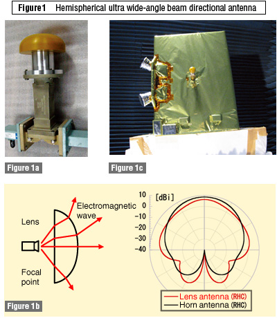
|
||||||||||