
Shinichi NAKASUKA - Professor, Graduate
School of Engineering, University of Tokyo -
Nobuyuki KAYA - Professor, Department of Computer and Systems Engineering, Faculty
of Engineering, Kobe University - |
Using the sounding rocket S-310-36, we conducted a basic
experiment on the deployment of a mesh structure, a candidate for constructing
large-scale space structures, and the transmission of microwaves with mesh-structured
phased-array antenna. The experiment was collaboration by the University of
Tokyo and Kobe University, with support from ISAS.
One solution for missions in outer space that require a large-area mesh or membrane
is to have small satellites hold the corners of the mesh/membrane structure
to deploy it and maintain its shape (known as the “Furoshiki (wrapping
cloth) satellite method”), not to deploy it by an extendible structure.
With the Furoshiki method, it is possible to extend structures up to several
kilometers, whereas the conventional method’s limit is estimated at several
100 meters. The Furoshiki method has significant technical challenges: how to
fold and stow the mesh/membrane in a small space; how to deploy a structure
without entanglement; what control is required for satellites to pull the mesh’s
corners, etc. A study of the complex dynamics, where multiple satellites and
mesh/membrane must interact with each other at deployment, is also important
as preliminary research.
One promising application for large-scale mesh/membrane structures is to form
a phased-array antenna by placing multiple transmission antennas on a structure.
Phased-array antenna technology, which works even with moving-antenna elements,
is indispensable in the realization of an ultra-large space antenna to be used
for a space solar-power satellite, ultra-high-speed communication, precise radar,
etc. The retrodirective method offers good control of the phased-array antenna.
This method keeps beams converged with a constant phase at the receiving points.
It works by measuring each antenna’s positional displacement using a pilot
signal from the ground and then altering the transmission phase to offset the
displacement.
 |
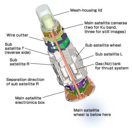
| Figure
1. Outline of the experiment system |
Sequence of the experiment
The experiment was conducted as a basic demonstration experiment
for the above technologies according to the following sequence.
| (1) |
One main satellite (MOT) and three sub satellites
(DAU-L, R, T) are stowed already linked together with wire and mesh in the rocket
fairing. The rocket is then launched. The mesh is housed at the top of the main
satellite (see Fig. 1 for an outline of the experiment configuration). |
 |
| (2) |
After the experiment system (including common
equipment) is released from the rocket at X+33sec, the wheel on the main satellite
cancels the residual spin of about 0.6Hz and stills the system (X+ 84.5 to 120sec). |
|
| (3) |
The mesh-housing lid is cut with a wire
cutter (X+130sec) and, then (X+133sec) the three sub satellites are released
by a spring at an initial speed of about 1.2m/sec with an interval angle 120deg
to the plane perpendicular to the rocket body axis (Fig. 2). At this event,
the main and sub satellites are in a bias-momentum state to maintain their attitudes. |
|
| (4) |
Deployment dynamics are measured by radiowave
sensors, which measure the distance between main and sub satellites, and INSs
(gyros and accelerometers) onboard both main and sub satellites. Simultaneously,
via a Ku-telemetry down-link, the deployment process is confirmed by images
(NTSC) shot by cameras on the main satellite directed at sub satellites L and
R, and a camera on sub satellite T directed at the main satellite. |
|
| (5) |
During and after deployment, various phased-array
antenna experiments are implemented using microwave transmitters/receivers installed
at the bottom of the main and three sub satellites. The key experiment is to
demonstrate that, with the adoption of the retrodirective transmission method,
antenna characteristics are maintained to some degree even if disturbances in
attitude and position occur with the satellites. |
|
| (6) |
We also conduct the following advanced experiment:
one-axis attitude control wherein the sub satellite positions the main satellite
in the center of its camera using gyros and image data; and thruster control
(only on sub satellites L and R) to prevent any bound back after the mesh deployment. |
|
| (7) |
When the mesh is deployed and stable (X+158sec),
we conduct another advanced test wherein an on-the-mesh moving system installed
on top of the main satellite crawls out onto the mesh. |
|
|
|
|