
“Larva” of next generation model
Picture of Figure 1 is the new X-band transponder, which is
expected to play a major role in the next generation. This is the trial model
produced to verify the newly-added basic functions. This is in the early stage
of development, so not qualified for use on satellite or explorer in space. But
its function and performance are the most advanced. Everything to communicate
is installed inside the box looking like four-tiered food box. The picture in
the front cover shows the testing scene with the cover opened and cables connected.
Table 1 shows the comparison of specification for three types of transponders.
The trial model is 15cm x 15cm x 9.45cm in size, is made of aluminum housing,
and weighs 3.4kg. Downsizing and lightweight are more emphasized than the past
transponders. Nevertheless, it is difficult to design in the way to produce the
cellular phone gathering the best of modern technologies. For transferring the
technology from right to left models, specialty of space technology is naturally
barrier for cost and, among others, reliability becomes the biggest issue.
The new transponder consists of four sections. From top they are: the base band
section to demodulate the receiving radio wave and to synchronize and regenerate
the signal (1st stage); the high frequency section to modulate and demodulate
the radio wave transmitted and received through antenna (2nd stage); the frequency
synthesis section to generate the radio wave with frequencies necessary for modulation
and demodulation (3rd stage); and the power supply section to distribute the power
necessary for the operation of transponder (4th stage). (Hereinafter, the term
of signal transmission or reception is used from the side of transponder.) The
base band section has also the function to regenerate the in-phase, or coherent,
radio wave that has frequency with the proper fraction ratio (880: 749) to the
received radio wave.
Feature of the new transponder is summarized as follows.
- Supporting X-band frequency channel for deep space exploration
- EImprovement of ranging (means “measuring distance”)
link quality in deep space exploration
- EImprovement of receiver sensitivity
- EDigital signal processing in the base band section
Considering these features, we call the new transponder
the “X-band digital transponder.”
In past, ISAS has had no transponder using X-band for transmission/reception,
except for that aboard the deep space explorer HAYABUSA launched in May 2003.
Frequency channel approved for the future deep space explorations is decided to
be higher frequency than X-band. We are, therefore, requested to introduce the
new transponder and use the X-band channel in the future. Well, as I use the term
of “X-band” without explanation in above, we generally call the radio
wave with 8GHz/7GHz frequency the “X-band.”
The X-band transponder was employed in HAYABUSA. But it is recognized that ranging
link in the deep space beyond 2AU (AU is astronomical unit. 1AU is the distance
between the Sun and earth, i.e., 150 million km) becomes a bottleneck. In other
word, we have difficulty in determining the trajectory of explorer. In order to
measure distance to explorers in space, first we send the radio wave carrying
the ranging signal from ground. The radio is returned to the ground, like boomerang,
via transponder aboard explorers. We measure the time from sending the signal
to receiving it to calculate the distance. In the past ranging, transponder aboard
explorers simply returned the radio wave. But, we adopt the new method that transponder
in space regenerates the signal, restores its quality, and re-modulates the signal.
And, then, it sends the ranging signal to the ground. In the conventional method,
quality of the ranging signal on the radio wave is deteriorated over its round
trip, up and down links. In the new method, the signal degradation occurs only
in one way. Figure 2 shows the experiment result of the two methods. In the conventional
method (upper), the ranging signal pattern is obscure due to interference by noise.
The new method (middle) shows that the original signal is finely regenerated (Please
see the correspondence in height level between the transmitted signal pattern
(bottom) and positions of the regenerated signal’s peaks.) Thanks to the
new method, it is expected that ranging link will be secured up to 5AU distance,
not sparing time in thinking about directivity of antenna or attitude control
of explorer. We believe that the new transponder has capability to enable the
exploration of Jupiter.
The digital signal processing must be the demands of the times, though, a little
belated. At long last, it becomes possible to obtain electrical components usable
in the space environment, while meeting the requirements of power consumption
and cost. The digitalization has the advantage, in addition to improvement of
receiver sensitivity, to enable elimination of the electrical adjustment process
peculiar to the microwave circuits, eventually leading to cost down. After improvement
of ranging link by the said ranging signal regeneration method, the communication
link between explorer and ground station becomes a new bottleneck. For this problem,
improvement of receiver sensitivity is very effective. By combination with the
new error-correcting code, the communication link can be also achieved to the
extent of 5AU distance. These performances have been confirmed by the experiments
using the trial model for functional evaluation shown in Figure 1.
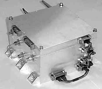
Figure 1 Trial Model of X-band Digital Transponder for Functional
Evaluation
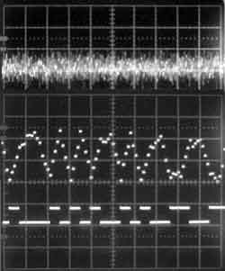
Figure 2 Effect of Ranging Signal Regeneration Method
Measurement result of the received ranging signal patterns under the same condition.
(Upper: conventional ranging method, Middle: regenerative ranging method, Bottom:
transmitted signal pattern)
|