

TOP > Report & Column > The Forefront of Space Science > 2005 > Hybrid Rocket “CAMUI”
![]()

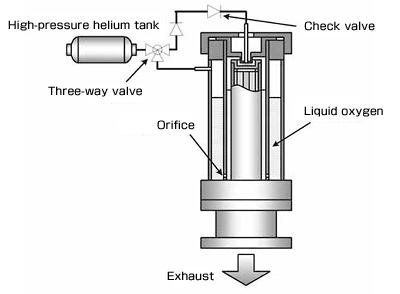
Development of a small body In order to use the hybrid rocket as a small launcher, the liquid-oxygen supply system must be incorporated into the small body in addition to the increase of thrust density. Liquid oxygen is non-explosive and non-hazardous, and, furthermore, we can expect to obtain high specific impulse from it. However, it is not easy to embed the supply system for liquid oxygen, a cryogenic liquid, into a small body. Take a valve for example: a cryogenic valve is larger than a common valve. Moreover, differing from the conventional type, the combustion chamber’s side wall is exposed to flame in the CAMUI system and thus requires cooling. In short, we have to embed a supply system equipped with a regenerative cooling system using cryogenic liquid in a small body. As a result of our deliberation on downsizing the valve and simplifying the regenerative cooling line, we devised a valve-less supply system (with no valves in the liquid oxygen flow line). Fig. 2 illustrates the concept. The liquid-oxygen tank is wrapped around the combustion chamber. Liquid oxygen flows through the space between the liquid-oxygen tank’s inner sidewall and the combustion chamber’s outer sidewall. The liquid oxygen flows through the orifice at the bottom of the tank, and then goes upward while cooling the chamber’s sidewall, before being injected into the chamber by an injector. There are no valves in the flow path from the liquid-oxygen tank to the combustion chamber. The regenerative cooling path is also very simple. Since the top of the liquid oxygen is under the injector, unless the tank is pressurized, liquid oxygen is not supplied to the combustion chamber. The pressurizing helium tank is connected to the liquid oxygen tank via a three-way valve. Before supplying the liquid oxygen, the valve prevents pressure rising in the liquid oxygen tank by releasing gasified oxygen into the combustion chamber.
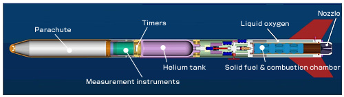
The steps before firing are as follows: Before ignition, gasified oxygen in the liquid-oxygen tank is released into the combustion chamber to fill the chamber. This allows easy ignition by applying electricity and heating the nichrome wire attached to the first block’s fore-end. Just after the moment of ignition, there is little thrust because the oxygen is supplied only by natural gasification. Just after confirmation of the ignition, the three-way valve switches to close the path releasing gasified oxygen into the combustion chamber and, at the same time, to open the line connecting the high-pressure helium tank with the liquid oxygen to start supplying liquid oxygen. In the actual launch procedure, the timing of this operation corresponds to the lift-off. Thus, we call the three-way valve the launch valve. By switching the valve, the thrust suddenly increases to normal combustion mode. Launch verification test To confirm that the valve-less supply system operates normally under a launch environment, we conducted a launch-verification test. Fig. 3 shows the outline of the launcher: 1.6m in overall length, 89mm in diameter and 50mm in inner diameter of the combustion chamber. Seven 35mm-high, cylindrical acrylic blocks are mounted in the combustion chamber. The total weight of the blocks is 450g.
The liquid oxygen tank is wrapped around the combustion chamber. The engine’s basic structure is almost the same as that shown in Fig. 2. The engine generates about 50kgf thrust by burning the 450g fuel for about four seconds. The launch valve is located above the engine and its handle is outside the body. By switching the launch valve with the actuator mounted on the launch pad, the launcher lifts off. The helium tank is above the launch valve. Space for payload is provided above the helium tank. The payload space has a cylindrical structure. The payload is expelled by a small explosive charge and pushes up the faring on the vehicle’s top. The raised faring splits into two and releases the parachute from the inside. The initial total weight of the body is 10.5kg. The highest altitude limit was set to about 900m for safety reasons. The launch experiments were conducted twice in March 2002 and January 2003 at Taiki-cho, Hokkaido. Both were successfully completed. For more detail of the launch experiment, please refer to: http://www.hastic.jp/camui/default.htm Launch services by our launcher for educational purposes, etc., are offered by Hokkaido Aerospace Science and Technology Incubation Center (HASTIC: http://www.hastic.jp/), an incorporated nonprofit organization (NPO).
|
||||||||